|
During this refit I will make some changes to the cockpit, Including:
-
Add
access hatches to improve access to the propeller shaft and the rudder
post stuffing boxes,
-
R&R diesel fuel fills,
-
R&R the rudder post top
bearing
-
Install a brace under the cockpit sole,
-
Replace and improve the forward cockpit drains,
-
Add
flush seat drains in the forward, outboard corners,
-
R&R the rudder stuffing box,
-
Add a
foot brace to the center of the cockpit
-
Restore the port cockpit seat locker
-
Build a new starboard cockpit
seat locker
-
Add
fiddles to the cockpit seats,
-
Tear
out old instruments, fill the holes and install new instruments
-
Install new teak coaming that box in the cockpit, and add new covering
boards, providing enough width to sit on the tops of the coamings,
-
Mount various hardware, including the winches,
-
Build a propane locker,
-
Reinstall companionway teak
-
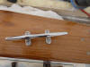
Add anchor chocks, and
-
Other
small improvements as I think of them.
Cockpit sole Access Hatches
I decided
that two hatches are really needed on Sally B: one to make work on the
propeller stuffing box and the aft end of the engine easier, and a second so
that I can adjust the rudder post stuffing box easily and quickly.
 I
am hoping I can gain a bit of storage space with the second access hatch as
well. I
am hoping I can gain a bit of storage space with the second access hatch as
well.
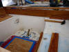
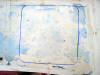
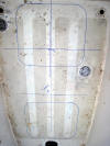 First
I measured approximately where the fuel tank is under the sole and
positioned the hatches around the tank as best I could. Then I marked the
locations on the sole and the approximate location of the tank as well. First
I measured approximately where the fuel tank is under the sole and
positioned the hatches around the tank as best I could. Then I marked the
locations on the sole and the approximate location of the tank as well.
The Bomar
hatches are very well built, aluminum painted in white Awlgrip, but when
installed will stand 1/4" proud of the cockpit sole. I don't want this
potential toe stubber than might cause me to trip some dark and stormy
night, so I will lay down a 1/4" sheet of fiberglass (from McMaster Carr) to
bring everything flush. The fiberglass sheet will be taken to 1/2" of the
edges of the sole to create a water drain channel. The rudder post top
bearing is also about 1/4" proud of the sole so it will be nicely flush as
well. I had it nickel plated years ago and it has taken on a nice almost
dull black appearance, but for this refit I may remove it and send it out to
be chromed.
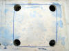
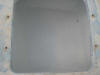
 After
sanding the cockpit sole smooth, I marked the forward hatch opening and
began the cuts. After
sanding the cockpit sole smooth, I marked the forward hatch opening and
began the cuts.
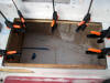
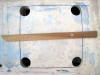
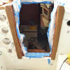
 To
keep the inside cutout piece from dropping down and binding the saw blade I
temporarily attached a couple of cross braces that would hold the cutout
piece in place. To
keep the inside cutout piece from dropping down and binding the saw blade I
temporarily attached a couple of cross braces that would hold the cutout
piece in place.
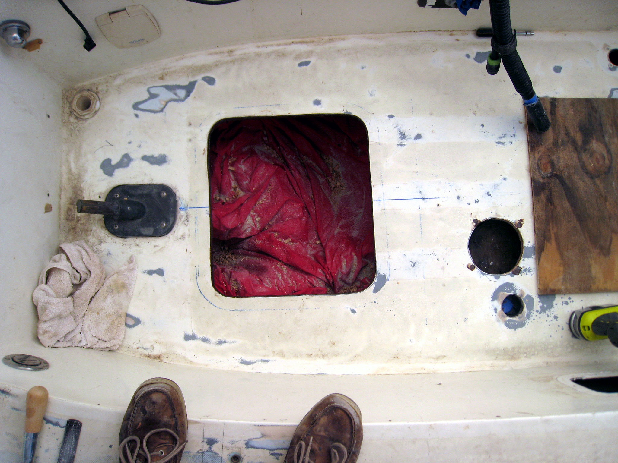
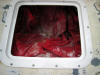
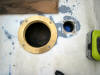
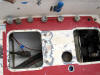
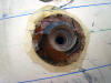
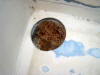
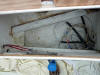
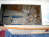
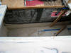
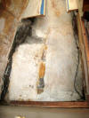
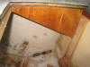
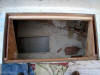
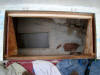
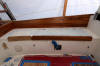
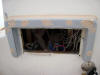
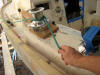
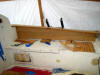
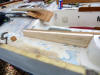
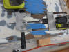
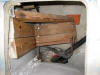
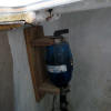
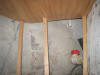
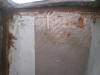
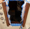
 Here
is the opening. You can see the forward side of the fuel tank, a PVC cross
conduit I installed in 1995 to carry the battery cables (I will remove it
since I an locating the batteries elsewhere in the boat). A surprise finding
when I studied the fuel tank closely: It has a clean out port just aft of
the aft edge of the cutout! Of course it is no good to anyone who hasn't cut
a giant hole in their cockpit sole--I sometimes wonder about the old Bristol
yard and some of the dumb things they did. Later I smoothed the edges and
beveled the top edge a little to match the inside flange bevel on the hatch
frame. I gouged out the balsa core all the way around the opening and pumped
in West Six10 to seal the core. Here
is the opening. You can see the forward side of the fuel tank, a PVC cross
conduit I installed in 1995 to carry the battery cables (I will remove it
since I an locating the batteries elsewhere in the boat). A surprise finding
when I studied the fuel tank closely: It has a clean out port just aft of
the aft edge of the cutout! Of course it is no good to anyone who hasn't cut
a giant hole in their cockpit sole--I sometimes wonder about the old Bristol
yard and some of the dumb things they did. Later I smoothed the edges and
beveled the top edge a little to match the inside flange bevel on the hatch
frame. I gouged out the balsa core all the way around the opening and pumped
in West Six10 to seal the core.
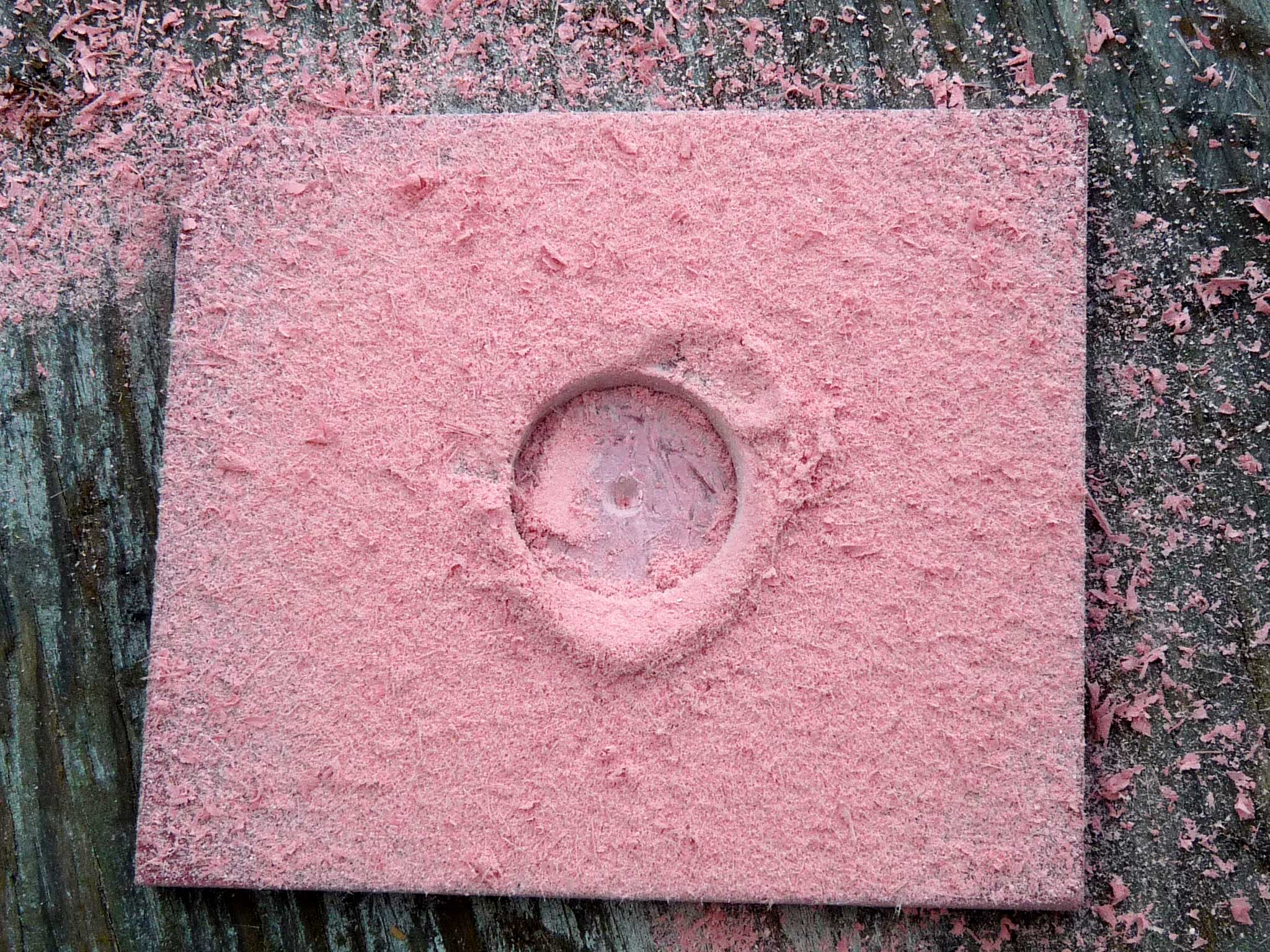
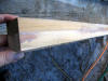
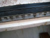
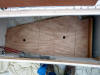
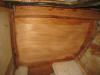
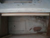
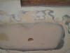
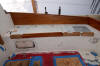
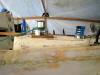
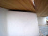
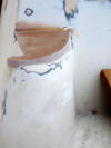
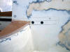
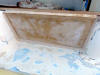
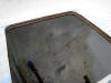
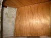
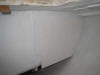
Note, that
on my boat, the core was in almost perfect condition--no signs of rot or
delamination. Here is a photo of the thickness of the cockpit sole: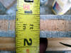 Finally I built two temporary covers for the two access hatch holes, and
called it a day.
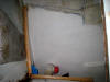
Finally I built two temporary covers for the two access hatch holes, and
called it a day.
Later,
when the epoxy had hardened, I overbored the mounting holes, and finally
drilled and tapped the 14 holes.
 Here
is the frame temporarily mounted (note that I used nylon washers under the
screw heads to prevent scoring the Awlgrip. Here
is the frame temporarily mounted (note that I used nylon washers under the
screw heads to prevent scoring the Awlgrip.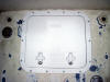 And
to the right is the hatch installed. The hatch has one weakness that anyone
using this hatch should be aware of. There are two pins in the forward edge
of the hatch (the opposite side from the latch side) that fit into holes in
the frame. The pins are stainless steel (it would have been better if Bomar
had used aluminum pins). To prevent corrosion between the two types of
metal, be sure to coat the pins and the holes liberally with Lanocote or a
similar product. I also plan to coat the neoprene gasket with silicone
grease. Once I determined that everything fit properly, I removed the hatch
and slipped it into an old pillowcase for protection. And
to the right is the hatch installed. The hatch has one weakness that anyone
using this hatch should be aware of. There are two pins in the forward edge
of the hatch (the opposite side from the latch side) that fit into holes in
the frame. The pins are stainless steel (it would have been better if Bomar
had used aluminum pins). To prevent corrosion between the two types of
metal, be sure to coat the pins and the holes liberally with Lanocote or a
similar product. I also plan to coat the neoprene gasket with silicone
grease. Once I determined that everything fit properly, I removed the hatch
and slipped it into an old pillowcase for protection.
 Next,
I addressed the aft access hatch. I repeated all the steps above to cut the
opening, over bore the mounting holes, and drill and tap the holes. I
fashioned a temporary plywood Next,
I addressed the aft access hatch. I repeated all the steps above to cut the
opening, over bore the mounting holes, and drill and tap the holes. I
fashioned a temporary plywood
 cover for the opening and stored away the
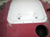
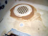
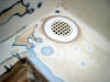
hatch until I finish painting the boat. Finally,
I cut an opening above the fuel tank cleanout cover for the opening and stored away the
hatch until I finish painting the boat. Finally,
I cut an opening above the fuel tank cleanout
 port for a deck plate, so that
between the open deck plate and the forward access hatch I could remove the
cleanout and clean the tank when necessary. The
steps are the same as above. I had on hand a 5" bronze deck plate that I
have decided to use for this. port for a deck plate, so that
between the open deck plate and the forward access hatch I could remove the
cleanout and clean the tank when necessary. The
steps are the same as above. I had on hand a 5" bronze deck plate that I
have decided to use for this.
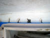
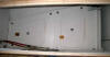
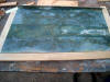
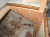
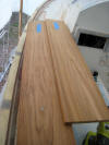
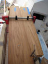
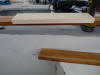
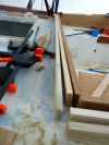
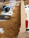
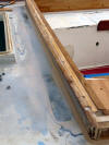
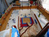
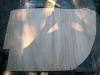
Today I
began cutting and fitting sheets of 1/4" fiberglass to raise the surface of
the cockpit sole even with the tops of the access hatches, the bronze deck
plate and the fuel fills.
 |
I have fitted the first two
pieces, each about 6" wide. I simply slip each piece under the lip
of the hatch and trace the outer edge; then cut with a saber saw. |
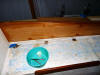
 |
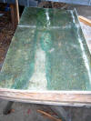
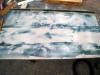
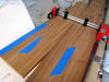
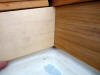
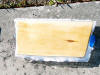
Here more pieces are fit
like a jigsaw puzzle. Any gaps will be filled flush with thickened
epoxy. |
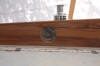
 |
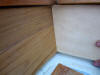
You can see here that I
have attached each piece with counter-sunk flat head screws. |
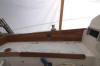
 |
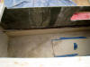
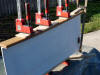
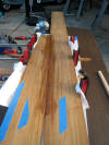
Here I have begun gluing
the panels in place. Some lead pigs help. |
 |
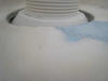
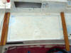
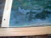
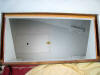
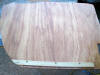
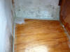
Here is the completed sole
showing the flush hatch. |
| |
|
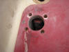
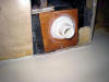
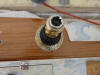
R&R Diesel Fuel Fills
Next to be
addressed are the two fuel fills. The first is located directly above the
original fuel tank. A source of constant puzzlement to me for a number of
years was finding traces of fuel in the engine compartment after sailing. I
would double check all the fuel line connects, retighten all the fittings
and clean up the fuel, only to find the same condition again after the next
sail. Eventually, quite by accident I discovered that the issue was a loose
hose clamp on the fuel fill. It is almost impossible to reach (and see) and
had never been tightened at the factory. when the boat was sailed hard and
heeled on a port tack, fuel would slosh up and out the loose connect and
drip into the engine compartment. The original fuel fill was an old bronze
thing and I will replace with a stainless steel fuel fill. In order to
fit, you need a Sea Dog fuel fill that has a collar to accept a tail piece.
You will have to use a Marelon tailpiece, and trim off the threaded side and
the hose barb side to make it fit.
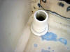
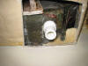
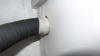
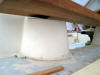
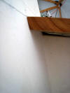
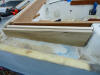
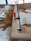
 There
is not much room. In fact as the photo shows, There
is not much room. In fact as the photo shows,
 only
1 inch from the underside of the sole to the top of the fill pipe. I will
replace the short piece of fill hose later. only
1 inch from the underside of the sole to the top of the fill pipe. I will
replace the short piece of fill hose later.
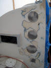
Next, I
gouged out the core from the fuel fill opening. I found some dry rot that
 extended
about an inch into the core, which I carefully cleaned out, and filled the
void with thickened epoxy. Then I turned my attention to the second fuel
fill. I added a second 25 gallon Nauta bladder diesel tank to the boat in
1995. The tank is suspended under the engine and has worked perfectly. The
best advantage to the bladder tank is that it extended
about an inch into the core, which I carefully cleaned out, and filled the
void with thickened epoxy. Then I turned my attention to the second fuel
fill. I added a second 25 gallon Nauta bladder diesel tank to the boat in
1995. The tank is suspended under the engine and has worked perfectly. The
best advantage to the bladder tank is that it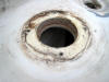 requires no vent so there is much less air in the tank and condensation is
not the critical issue it is with a normally vented tank. After removing the
fill hose and sealing the end with tape, I removed the fuel fill and found
no sign of water. I gouged out the coring around the edge of the hole and
filled it with thickened epoxy.
requires no vent so there is much less air in the tank and condensation is
not the critical issue it is with a normally vented tank. After removing the
fill hose and sealing the end with tape, I removed the fuel fill and found
no sign of water. I gouged out the coring around the edge of the hole and
filled it with thickened epoxy.
 When it hardens, I will overbore the
mounting holes, drill and tap them for new fasteners. Here the attachment
holes are being overbored to mount one of the fuel fills to the new sole. When it hardens, I will overbore the
mounting holes, drill and tap them for new fasteners. Here the attachment
holes are being overbored to mount one of the fuel fills to the new sole.
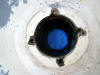
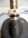
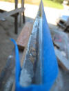
R&R the Rudder Post Top
Bearing
The last
time I had it off was in 1995. It was more silver then but being plated in
nickel it has tarnished the same way nickel tarnishes I suppose.
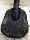 |
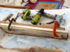
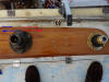
The bearing with the screws
removed. It was tough pulling it off the shaft but it eventually
worked loose. |
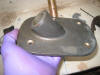 |
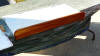
It is a lovely piece of
bronze casting. The yard had them chrome plated but that wore off
many years ago. |
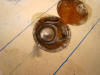
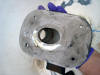 |
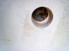
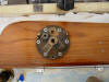
The underside of the
casting. |
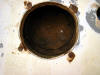
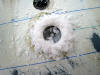
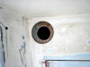
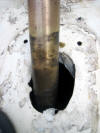 |
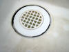
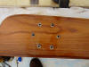
The hole in the cockpit
sole. |
| The rudder post
bearing is a fairly tight fit, but it is not lubricated, nor does it
seal out any rain water or sea water, a slight bit would leak past,
so I will seal both ends of the bearing and pump it fill of
waterproof grease. First I ordered from McMaster Carr:
neoprene o-rings
90025K403
(Same as 90025K12) |
|
Double Seal Buna-N O-Ring AS568A Dash Number 322 |
|
Teflon o-rings
9559K121
(Same as 9559K1) |
|
PTFE O-Ring AS568A Dash Number 026 |
|
and a locking nylon
collar
|
60475K78 |
|
Nylon Set Screw Shaft Collar 1-1/4" Bore, 2" Outside
Diameter, 11/16" Width |
|
|
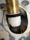 |
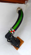
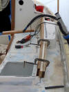
Here, you can see from top
to bottom, the Teflon bearing (used to provide permanent lubrication
between the rudder post bearing and the o-ring seal, the black
o-ring seal, and the silicone tape I wrapped around the rudder post
to prevent the bearing and seal from slipping down the rudder post. |
 |
Here, you can see from
bottom up, is the rudder post bearing, the Teflon o-ring bearing,
the rubber o-ring seal and a nylon sleeve that locks to the rudder
post with a stainless set screw. All this will be pushed down onto
the top of the bearing after it is filled with grease. It will
prevent any play in the rudder post bearing, permanently lub the
rudder post and seal it from moisture. |
How to
keep the rudder from lifting up off the lower pintel--for instance if you go
onto a reef (or if, God forbid, the boat does a 360)? I built and installed
a stop under the top bearing to prevent the rudder from
lifting.
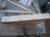
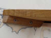
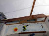
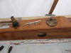
Cockpit Sole Brace
While the
cockpit sole has no issues with delamination or core rot, it does flex a
slight bit when I
 step
down hard from the cockpit seat. I decided now is a good time to address the
issue by building and installing a brace under the sole to stiffen it up. I
took some scrap step
down hard from the cockpit seat. I decided now is a good time to address the
issue by building and installing a brace under the sole to stiffen it up. I
took some scrap
 teak
and laminated a 2" x 2-1/2 inch floor. consisting of three pieces glued
together in a "T" arrangement. I cut the floor the wide of the cockpit (it
butts against the vertical sides of the engine box under the sole). I used
Locktite PL Premium polyurethane construction adhesive to glue it in place
(which is as tenacious as 5200). Once the adhesive set up, I overbored 1"
holes thru the coring above the brace, a total of six holes, where I would
mount 1/4" carriage bolts to thru-bolt the sole to the brace. teak
and laminated a 2" x 2-1/2 inch floor. consisting of three pieces glued
together in a "T" arrangement. I cut the floor the wide of the cockpit (it
butts against the vertical sides of the engine box under the sole). I used
Locktite PL Premium polyurethane construction adhesive to glue it in place
(which is as tenacious as 5200). Once the adhesive set up, I overbored 1"
holes thru the coring above the brace, a total of six holes, where I would
mount 1/4" carriage bolts to thru-bolt the sole to the brace.
 |
Then I used two different
sized forstner bits to machine out a recess for the head of the
carriage bolt, and a deeper recess for the carriage bolt shoulder. |
 |
Once the two recesses were
cut, I drilled a pilot hole using the portable drill press and
finally a 1/4" hole for the carriage bolt. |
 |
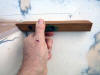
Here you can see the
recessed head of a carriage bolt. |
 |
The six bolts were inserted
and then thickened epoxy filled the recesses covering the bolt
heads. |
 |
I added fender washers and
nylock nuts and blue Loctite. |
The brace
has completely eliminated the slight flex in the cockpit sole.
Cockpit Drains
The B29
cockpit drains are merely formed fiberglass nipples in the cockpit sole. At
one time they had smallish grates that screwed down over them into a recess,
but hell if I know what happened to them. To match the Marelon thru hulls I
added as additional drains at the aft end of the the cockpit I will install
Marelon scuppers at the forward side as well. For now I have
decided to leave the forward cockpit drains alone. They are structurally
strong and safe, just not especially attractive. I will use the Marelon
drains for the seat drains instead.
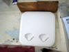
Seat Drains
The seats
drain via the drain channels in the cockpit seat lockers now, but so as not
to overwhelm the channels and to get the last bit of water off the seats, I
will install two drains at the forward, outboard corners of the seats that
will keep the seats clear of water and add two more (a total of 6 drains
now) for the cockpit).
 |
The drains are located about 1/2" inboard to the forward seat
corners. |
 |
I
used a 2-7/8" forstner bit to cut the top layer of glass off the
seats. Then I painted the balsa with epoxy. I will use a 2" hole saw
to finish cutting thru the seats. |
 |
Here you can see the depth of the cut. The Marelon drains will be
set in thickened epoxy and permanently glued in to the seats. |
 |
I
used the center point of the forstner bit to center a 2" hole saw
and cut thru the remaining material. |
 |
Here is the drain test fit. I am not overly concerned with how it
sits in the flange since I will epoxy the drain permanently through
the seat. |
 |
I
used my Fein Multimaster to cut out a square of the damned liner to
get at the underside of the port cockpit seat. The drains are inside
the cabin and each inside a locker, but the hoses will make an immediate turn aft thru a hole
in the cockpit locker bulkheads to the cockpit, then a turn to
outboard and down to
Marelon seacocks and thru-hulls at the waterline (giving me a total
of 6 1-1/2" drains for the cockpit). |
 |
I
slathered up the flange with very thick epoxy (404) and squished the
drain into it. Once the epoxy begins to gel I will fill with more to
eliminate any cavities. |
 |
Once the thickened epoxy set, I dribbled in epoxy mixed lightly with
410 thickener. When it is fully cured I will sand everything flush
with the Festool Rotex. |
 |
Here you can see the finished hose barb. I used a plywood backing
block saturated with epoxy as a flat surface. |
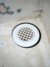
 |
The finished port seat
drain. |
 |
Starboard Marelon thru-hull
glued in thickened epoxy and a 1-1/2" Marelon seacock installed onto
an epoxy saturated plywood backing block. |
 |
The drain hose attached
with two AWAB 316 stainless hose clamps. |
 |
The hose attached to the
deck drain, again with two AWAB 316 stainless hose clamps. |
 |
To prevent any possibility
of chafe to the hose I wrapped some Teflon sheeting around the hose
where it passes thru the bulkhead and secured it with a zip tie. |
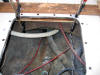
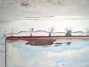
R&R the Rudder Stuffing Box
Once I cut
the opening for the aft access hatch, I got the the most lovely view of the
rudder stuffing box. The last time I saw this baby it was in 1995, when I
was stuffed upside down in the lazarette, and by the light of a droplight,
changed out the stuffing box hose (which was shot) all the hose clamps, and
repacked the collar. Here is a photo: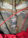 As you can see it looks brand new and recently rebuilt, the hose is stiff
but slightly pliable, the hose clamps look fine. I will check the packing
but everything else about this task is done.
As you can see it looks brand new and recently rebuilt, the hose is stiff
but slightly pliable, the hose clamps look fine. I will check the packing
but everything else about this task is done.
Cockpit Sole Foot Brace
The good
news about the B29 is the enormous cockpit. You can throw a big party there,
and can seat everyone very comfortably while sailing. The bad news about the
B29 is the enormous cockpit. The cockpit is simply too wide for sailing
unless you are an NBA center. I have always installed some sort of foot
brace on the cockpit sole to brace my feet against when I am sailing on the
high side.
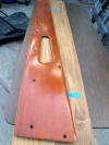
Restoring the
port cockpit seat Locker
 The
Bristol yard used stainless steel piano hinge on the lid of the port cockpit
seat locker. The problem with the piano hinge is that it is screwed into the
thin back edge of The
Bristol yard used stainless steel piano hinge on the lid of the port cockpit
seat locker. The problem with the piano hinge is that it is screwed into the
thin back edge of the lid and the edge of the cockpit seat with a lot of tiny #6 screws. The
result after lots of stress and 40 or so years are cracks and thin breaks in
the glass and gelcoat. A better, cleaner method would be surface mounted
hinges, which would be considerably stronger than the dinky piano hinge, so
for the existing port locker lid and for the yet to be built starboard
locker lid I will remount both with surface mounted hinges.
the lid and the edge of the cockpit seat with a lot of tiny #6 screws. The
result after lots of stress and 40 or so years are cracks and thin breaks in
the glass and gelcoat. A better, cleaner method would be surface mounted
hinges, which would be considerably stronger than the dinky piano hinge, so
for the existing port locker lid and for the yet to be built starboard
locker lid I will remount both with surface mounted hinges.
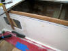
 First
I removed the lid and went about repairing the cracked gelcoat in the edge
of the cockpit seat and First
I removed the lid and went about repairing the cracked gelcoat in the edge
of the cockpit seat and
 filled
in the multitude of holes in the outboard edge of the lid. I opened up each
of the cracks in the gelcoat and then filled the holes and cracks with
unthickened epoxy. I also filled the holes in the lid by turning it on its
edge and letting epoxy soak into all the holes and indentations. Once the
epoxy had cured I sanded everything smooth and flush. filled
in the multitude of holes in the outboard edge of the lid. I opened up each
of the cracks in the gelcoat and then filled the holes and cracks with
unthickened epoxy. I also filled the holes in the lid by turning it on its
edge and letting epoxy soak into all the holes and indentations. Once the
epoxy had cured I sanded everything smooth and flush.
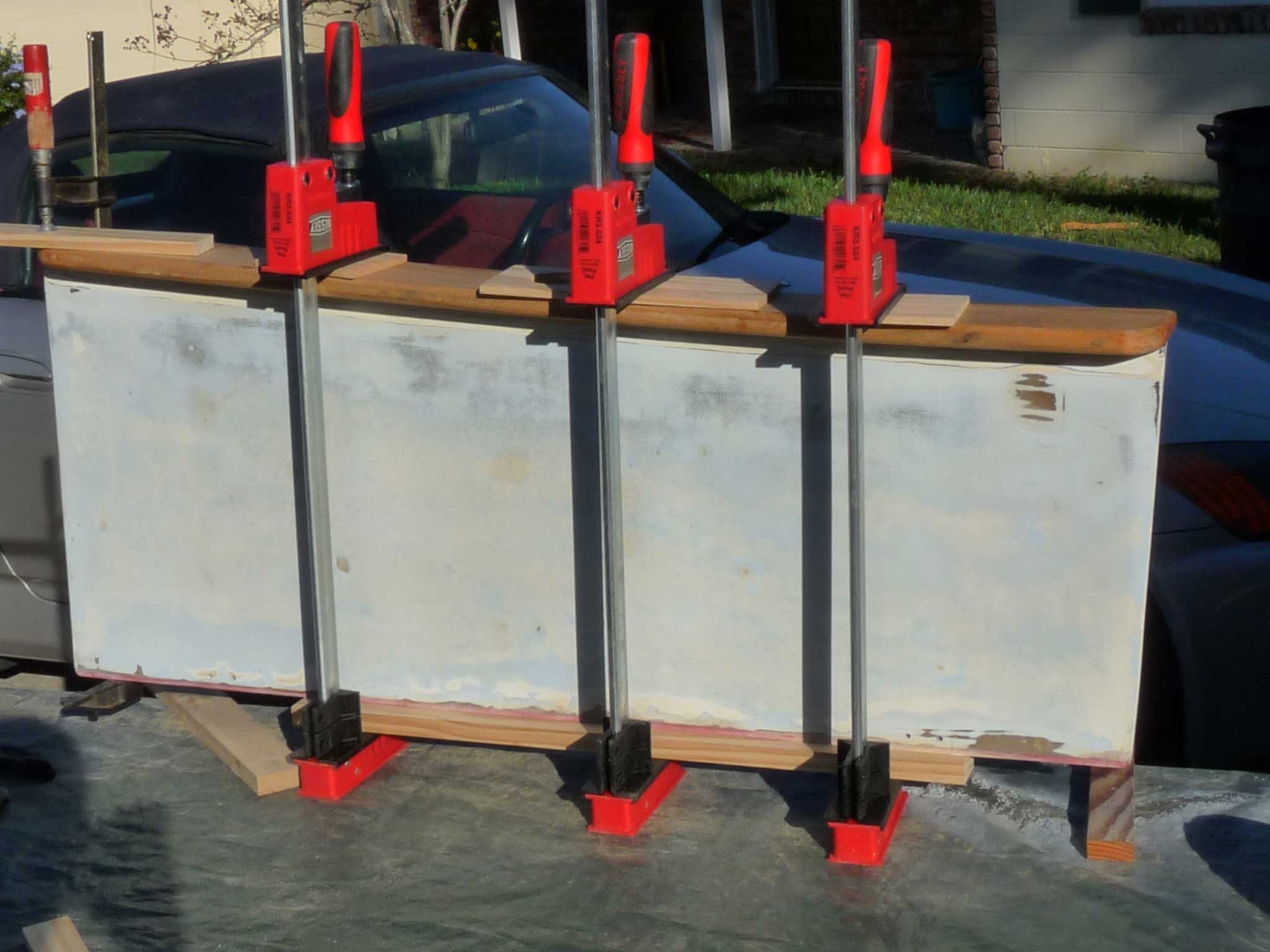
T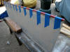 he
lid was cut about 1/4 inch short to accommodate the fold of the piano hinge,
so the next step was to add 1/4 inch back to the outboard edge of the lid. I
used some fiberglass from McMaster Carr for this, gluing it in thickened
epoxy. he
lid was cut about 1/4 inch short to accommodate the fold of the piano hinge,
so the next step was to add 1/4 inch back to the outboard edge of the lid. I
used some fiberglass from McMaster Carr for this, gluing it in thickened
epoxy.
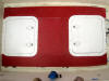
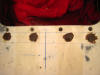
 Again,
after curing and sanding and shaping, the back additional material made a
much smaller gap (which will eventually be sealed from water with a gasket).
Later I added two layers of 6 oz cloth to the underside of the outboard edge
to strengthen the addition of the red fiberglass. Again,
after curing and sanding and shaping, the back additional material made a
much smaller gap (which will eventually be sealed from water with a gasket).
Later I added two layers of 6 oz cloth to the underside of the outboard edge
to strengthen the addition of the red fiberglass.
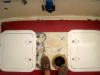
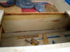
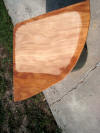
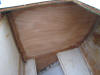
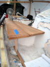
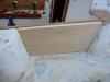
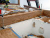
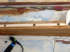
 Once
the lid was finished, I removed the wiring from the locker, removed the
hoses, and prepared to paint it out. Before painting, I decided to build a
temporary floor for the locker to help organize the junk that fills up all
cockpit lockers. The floor would have two hatches. It would be recessed back
from the forward bulkhead a few inches to accommodate the hoses that attach
to the bulkhead with siphon brakes, and have a fiddle at the front end to
prevent small items resting on the Once
the lid was finished, I removed the wiring from the locker, removed the
hoses, and prepared to paint it out. Before painting, I decided to build a
temporary floor for the locker to help organize the junk that fills up all
cockpit lockers. The floor would have two hatches. It would be recessed back
from the forward bulkhead a few inches to accommodate the hoses that attach
to the bulkhead with siphon brakes, and have a fiddle at the front end to
prevent small items resting on the
 floor
from dropping into the lower part of the locker. Finally the entire floor
would be removable with a few screws so that should I really need better
access to the bottom of the locker it would easy enough to remove the floor.
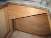
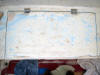
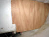
Here is the floor in position but not yet painted out or screwed down. floor
from dropping into the lower part of the locker. Finally the entire floor
would be removable with a few screws so that should I really need better
access to the bottom of the locker it would easy enough to remove the floor.
Here is the floor in position but not yet painted out or screwed down.
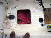
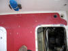
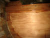
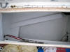 Here
is the port cockpit painted out. And this shot shows the port seacock for
the port seat drain. Here
is the port cockpit painted out. And this shot shows the port seacock for
the port seat drain.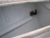
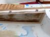
 Finally,
here is the finished removable floor. Finally,
here is the finished removable floor.
Bristol
covers the drain channels for the port cockpit locker and then drills holes
in those two covers--which contribute to them becoming blocked with dirt and
limits the amount of water that can be handled. So I used my Fein
Multimaster to open up some of the holes Leaving enough material for
strength).
New Starboard Cockpit Locker
Next, I
need to build a new locker in the starboard seat, over what used to be the
starboard
 quarterberth.
I measured where I feel that it needs to be--slightly aft of the port locker
to afford more cupboard space in what will be come the galley, and a lid not
as long as the port side. Then I hot glued battens to guide the jig saw to
make quarterberth.
I measured where I feel that it needs to be--slightly aft of the port locker
to afford more cupboard space in what will be come the galley, and a lid not
as long as the port side. Then I hot glued battens to guide the jig saw to
make
 good
clean cuts. good
clean cuts.
 First
I cut the two short sides, then glued batten lengthwise to support the lid
for the other two cuts. Here is the opening. Next is to clean up the
underside of the lid and even the thickness so it will compress weather
stripping evenly. I build a form around the two sides and the hinge side out
of 3.4 inch stock that seemed to match the thickness of the lid in most
areas. I will use the Festool Rotex to even out the lid down to the
thickness of the surrounding form First
I cut the two short sides, then glued batten lengthwise to support the lid
for the other two cuts. Here is the opening. Next is to clean up the
underside of the lid and even the thickness so it will compress weather
stripping evenly. I build a form around the two sides and the hinge side out
of 3.4 inch stock that seemed to match the thickness of the lid in most
areas. I will use the Festool Rotex to even out the lid down to the
thickness of the surrounding form
 |
Here is the form built
around the lid. |
 |
I am just starting to level
the inside of the lid to the thickness of the form. |
 |
First fairing of the lid. |
 The
inboard side of the locker is only 1/4" fiberglass and pretty flimsy so to
create an even foundation for the drain channels and to stiffen up the side
I will glue two layers of 1/4" plywood to the inside. Using 1/4" material
will let it easily take the slight curve of the cockpit seat without
deforming it--which would affect the fit of the locker lid when closed.
Before adding the plywood, I need to create a stop for the lid along the
inboard edge which will help brace up the inboard wall of the cockpit
seat/locker; give me a formed bearing surface for the lid to rest on
when it's closed, and seal the locker. The
inboard side of the locker is only 1/4" fiberglass and pretty flimsy so to
create an even foundation for the drain channels and to stiffen up the side
I will glue two layers of 1/4" plywood to the inside. Using 1/4" material
will let it easily take the slight curve of the cockpit seat without
deforming it--which would affect the fit of the locker lid when closed.
Before adding the plywood, I need to create a stop for the lid along the
inboard edge which will help brace up the inboard wall of the cockpit
seat/locker; give me a formed bearing surface for the lid to rest on
when it's closed, and seal the locker.
The tricky
part is duplicating the curve of the inner side of the seat--the inboard
side of the seat is flimsy enough that if I'm not careful the batten could
reshape the slight curve and the lid would no longer fit. First I considered
scribing and cutting the curve on my band saw, but I decided instead to use
a 1"x1" teak batten, cut the length of the seat and glued in place. I found
by experimenting that the curve of the inner lip of the lid was the same as
a 3/8" round over router bit, so I applied a round over to the inner corner,
and glued it in place with Six10 epoxy. By bracing the batten at each end to
the shape of the inboard side of the seat locker, the batten took the exact
same curve as the inboard edge of the lid.
 |
Here is the inside of the
locker showing the position of the batten. |
 |
And the outside showing the
round over. |
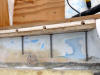
The next
step is building up the inside of the inboard locker wall with two sheets of
1/4" plywood. I cut the layer to size and painted the glue-to side and the
edges with unthickened epoxy. Then I used a tube
 of
Six10 to apply a thick bead of the epoxy everywhere, especially around
the edges of the port hole I will fill. Then, using a brace at each end and
some wedges, I installed the plywood and wedged it in place. Tomorrow when
theSix10 is fully cured, I'll remove the braces and wedges and glue up a
second 1/4" sheet. of
Six10 to apply a thick bead of the epoxy everywhere, especially around
the edges of the port hole I will fill. Then, using a brace at each end and
some wedges, I installed the plywood and wedged it in place. Tomorrow when
theSix10 is fully cured, I'll remove the braces and wedges and glue up a
second 1/4" sheet.
Today I
determined where to position the bulkhead separating the new starboard
locker from the interior of the boat. The bulkhead will be about 12 inches
recessed into the locker to give me some deep cabinets for the galley. Once
the position was established, I made a square cut across the quarter berth,
from the inside wall of the locker to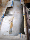 the edge of the hull - as close as I could get with the jig saw. When I get
a new blade for the Fein Multimaster, I will finish the cut and remove the
tabbing for the berth against the hull. Then I cut out the remainder of the
quarter
the edge of the hull - as close as I could get with the jig saw. When I get
a new blade for the Fein Multimaster, I will finish the cut and remove the
tabbing for the berth against the hull. Then I cut out the remainder of the
quarter
 berth inside the cabin.
After installing a new blade in the Fein, it made fast work of the tabbing
against the hull and the remaining pieces of plywood. berth inside the cabin.
After installing a new blade in the Fein, it made fast work of the tabbing
against the hull and the remaining pieces of plywood.
 |
The starboard cockpit locker bulkhead. cut from 1/2 hardwood
plywood, sealed in epoxy and ready to be installed. |
 |
Here it is shown glued in Six10 and screwed in place. I still need
to tab it to the hull which will be done on the cabin side of the
bulkhead. |
 |
Showing the cabin side: the bulkhead has been tabbed to the hull
with two layers of 24 oz biax tape, and glued to the hull and
underside of the deck and cockpit seat with Six10 epoxy. A 3/4"
maple beam was installed to provide additional strength to the
bulkhead. |
 |
Showing the locker side, a 2x4 cedar beam was installed opposite the
maple support beam on the other side of the bulkhead and the two
beams bedded in thickened epoxy and screwed together with 1/4"
stainless screws. The small irregular gaps to the underside of the
cockpit seat and side deck are filled with Six10 epoxy. |
 |
Next, I started building
the gutters for the locker. the first step was to glue battens to
the underside of the seat. I used 1-1/2" by 3/4" stock from Lowes,
glued with Six10 epoxy. |
 |
Here is the start of the
forward hatch gutter for the starboard locker. The depth is 8", the
same as the port locker. This gutter side is recessed so it is flush
with the edge of the opening. It will fasten against the top and
left battens already installed. |
 |
Here is the inside of the
aft hatch gutter, also recessed so it fits flush and will be
fastened against similar battens. (the wide angle lens makes the
seat look curved--sorry about that!) |
 |
Here you can see the start
of the inner side of the aft hatch gutter. |
 |
The inner side of the
gutter is spaced 3/4". |
 |
Here is the forward inner
side of the hatch gutter, positioned where it will eventually be
fastened. |
 |
To protect the plywood from
any possible water intrusion where the drain holes will be cut, I
will over bore the holes and insert and glue flush PVC tubing. |
 |
Here is the start of the
outboard (hinge-side) gutter. |
 |
I have attached the bottom
of the three sided "box" of the gutter--1/3" ash. |
 |
And epoxied the bottom to
the outer side of the gutter. After I glue and screw the inner side
in place I will glue and screw the bottom to the inner side as well. |
 |
Here I am gluing the
hinge-side gutter. |
 |
All the various pieces (about a dozen) are dry fit for the last
time. |
 |
Before gluing and final assembly the drain holes are bored with a
forstner bit. Then, I saturated the inside of the holes with
unthickened epoxy, slathered up the PVC tubes with Six10 and
inserted them. |
 |
The thickness and plywood layers to the starboard locker side. |
 |
I
have mounted the hinges just to see how everything fits. The front
edge needed some adjustment (sanding) to get a solid fit. |
 |
Here are the finished gutters for the cockpit locker. Still
requiring some paint, which I will apply soon. |
 |
And, the finished item sporting a nice small barrel bolt to lock
down the locker door. |
Cockpit Seat Fiddles
Short
fiddles along the edge of the seats also help keep me planted on the seat
when the boat is heeling as well as keep my feet from slipping off the seat
when I am stepping back into the cockpit from the high side. They also keep
little things from sliding off the seat. Since the seat height is short, the
fiddles don't become an annoyance against the back of the legs while
sitting. The fiddles are made from the scrap after cutting the coamings and
covering boards: they rise above the level of the seats 1-1/4 inch. First, I
machined fiddles for the two seat locker lids.
 |
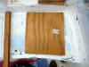
The teak fiddles are designed to fit the front face of each
lid--this is the larger original port lid. For each lid there will
be additional pieces of teak machined for the bottom of the fiddle
to butt against, making a more water proof seal. |
 |
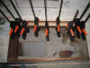
The fiddles are not screwed; simply glued with epoxy thickened with
404 adhesive filler and clamped. |
 |
After two days of curing I removed the bar clamps, sanded the
fiddles and applied a coat of thinned epoxy to seal the wood. |
 |
Fiddles complete on port seat. |
 |
Fiddles complete on starboard seat. The indention in the middle
fiddle is to accommodate the autopilot. |
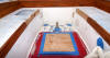 |
Photo of completed fiddles. |
New Instruments
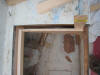
As part of
the new instrumentation in the cockpit, I built a wood frame to
 received
a plexi cover and protect the Yanmar engine gauge panel from water. The
frame is built from some poplar and is simple enough, and as you can see in
this shot I cut an 1/8" groove in the inside edge to hold the plexi. received
a plexi cover and protect the Yanmar engine gauge panel from water. The
frame is built from some poplar and is simple enough, and as you can see in
this shot I cut an 1/8" groove in the inside edge to hold the plexi.
 I
mounted the frame to the aft cabin bulkhead, glued with West Six10 and
screwed, and later filled the holes and I
mounted the frame to the aft cabin bulkhead, glued with West Six10 and
screwed, and later filled the holes and
 formed
a fillet around the frame with epoxy thickened with 410. A few days later
when the epoxy had fully cured, I sanded everything smooth, as well as
filling the holes left by the old instruments. Note that the bottom hole
filled was for the 120V power inlet for shore power. I have decided with
this refit to not use a shore-power battery charger or have 120 volts on the
boat at all. The batteries will be maintained with solar; and I will feel
better not having the boat connected electrically to any marina. formed
a fillet around the frame with epoxy thickened with 410. A few days later
when the epoxy had fully cured, I sanded everything smooth, as well as
filling the holes left by the old instruments. Note that the bottom hole
filled was for the 120V power inlet for shore power. I have decided with
this refit to not use a shore-power battery charger or have 120 volts on the
boat at all. The batteries will be maintained with solar; and I will feel
better not having the boat connected electrically to any marina.
Teak Coamings and Covering
Boards
Just a
personal thing, but I really dislike mahogany. It is a very soft wood, likes
to split, has a dull, uninteresting grain, turns black at the first hint of
moisture. I have never been a fan of the mahogany coamings on the Bristol:
they attach with screws so they look very temporary, they leak at the
outboard side where they abut the side decks and they simply don't look
integrated with the boat. So I will build new teak coamings, permanently
glued to the boat and cover the tops of the winch islands and top edges of
the coamings with teak covering boards.
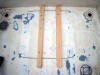
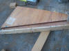
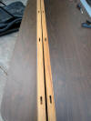
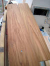
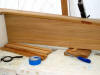
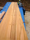
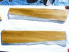
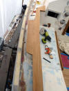
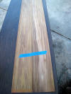 The
first step in constructing the coamings and their covering boards is to edge
join some teak planks together. I began by matching the grain of the
different planks together as much as possible. The planks are 7 inches wide
and I need at least 11 inches for the maximum height of the coaming boards.
I found reasonable grain matches between the four boards' two sides and
noted the relations with some tape across the boards. The
first step in constructing the coamings and their covering boards is to edge
join some teak planks together. I began by matching the grain of the
different planks together as much as possible. The planks are 7 inches wide
and I need at least 11 inches for the maximum height of the coaming boards.
I found reasonable grain matches between the four boards' two sides and
noted the relations with some tape across the boards.
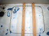
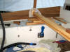
 To
join the boards I laid out the port coaming first, and drew the outline of
the old coaming board onto the two boards, using the outline as a reference To
join the boards I laid out the port coaming first, and drew the outline of
the old coaming board onto the two boards, using the outline as a reference
 to
see where the joint occurred and where to apply Domino tenons. Then I used
my Festool Domino cutter to drill the mortises, being careful not to drill a
mortise too close to the slopping top edge where the coaming would be cut. to
see where the joint occurred and where to apply Domino tenons. Then I used
my Festool Domino cutter to drill the mortises, being careful not to drill a
mortise too close to the slopping top edge where the coaming would be cut.
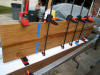
To join
the edges I followed the same procedure I always follow when gluing teak: I
carefully and repeatedly cleaned the two surfaces with acetone and a white
rag until the rag came away clean and
 no
longer stained tan from the teak oil. I then painted both surfaces with
unthickened epoxy and let it soak in for a while. Finally, I ran a
bead of Six10 along no
longer stained tan from the teak oil. I then painted both surfaces with
unthickened epoxy and let it soak in for a while. Finally, I ran a
bead of Six10 along
 both
edges and into each mortise and thoroughly around all the edges of the
tenons; inserted the tenons, pressed the two planks together, and carefully
clamped them. The brilliance of the Festool tenons is that they act as
extremely accurate reference points and the two planks were an exact fit. both
edges and into each mortise and thoroughly around all the edges of the
tenons; inserted the tenons, pressed the two planks together, and carefully
clamped them. The brilliance of the Festool tenons is that they act as
extremely accurate reference points and the two planks were an exact fit.
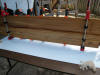
Once the
Six10 hardened, I took the board inside and did the same joining to the
starboard coaming. Six10 seems to take a full 24 hours or more at room temps
to thoroughly harden and a full cure will take a week, so I will cut the
planks to the shape of the coamings, but will wait a week until I start to
bend and dry fit them into the curved sides of the cockpit.
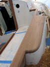
While the
coamings are curing I took a look at how I will build and install the
covering boards. The covering boards cover the top edges of the coamings,
the tops of the winch islands and provide a caprail around the cockpit wide
enough to sit on
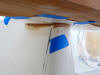
 |
Here are the two covering boards roughly laid out, using some lead
pigs to hold them in position. |
 |
I
want to put some temporary screws through the two planks and into
the winch island to hold them firmly where I want them. But first I
need to determine where the winches will be located based on the new
genoa track hardware. |
 |
Turns out each winch will be moved aft about 8 inches which will
make them more accessible to the tiller when I am singlehanding. Now
that I know where the winch bases will be I drill and screw some
screws under the eventual bases to stabilize the planks. |
 |
I
need to join a second width board to the two primary planks to get
the width needed to handle the curve of the cockpit sides, and
overlap the tops of the coaming boards on each side. |
 |
The forward bases for the coamings, that attach to the cabin sides
is a bit lower than the winch islands. I will have to build up this
base probably with thickened epoxy. |
 |
The second plank for each side of the covering boards needs to fit
between the outer plank and the cabin side in order to accommodate
the front base of the coamings. The edge against the cabinside was
cut at an angle matching the angled side of the house, and second
board scribed against the outer board and cut to fit. |
 |
Another shot of the port covering board. |
 |
I
set one domino tenon at the front of the assembly and glued the two
port boards together with Six10 epoxy. |
 |
Here I am fitting the second board on the starboard side. |
 |
Here is the port covering board glued up and sanded lightly to
eliminate the glue line. |
 |
It
fits very nicely to the side of the cabin. |
 |
The gap that needs filling--probably with epoxy and then shaped with
a sander. |
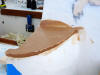
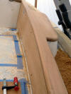
 |
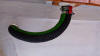
Starting to fit the starboard coaming the the underside of the
covering board. First I need to bend it to the curve of the cockpit
so I will jury rig a car jack for that purpose. |
 |
A
closer view of the starboard coaming being rough fit to the covering
board. |
 |
I
am using my Honda's jack to force the two coaming boards out to the
curve of the cockpit sides. |
 |
To
fill the gap between the covering board and the forward mounting
flange for the coaming, I covered the affected area of the teak
board with freezer paper, and added very thick epoxy to the top of
the flange, roughly fairing the edges. After the epoxy cures I will
remove the board and paper and clean up the epoxy with a sander. |
 |
Here is the fully cured epoxy
after removing the covering board and the freezer paper. |
 |
And here I am fairing the epoxy
to the shape of the forward coaming mounting flange with my Rotex. |
The next
step in the new coamings is to measure and cut the aft coaming that mounts
athwartships at the aft end of the cockpit. It is a bit tricky to measure as
the sides of the coamings are slanted outboard, and curve in
 slightly
at the aft end. I thought it best to start with a template which I made from
some scrap poplar. I used a sliding bevel to take off each of the four
angles--two to each side--and cut template on my table saw. slightly
at the aft end. I thought it best to start with a template which I made from
some scrap poplar. I used a sliding bevel to take off each of the four
angles--two to each side--and cut template on my table saw.
 |
Here is the port side edge,
with the template jigged in place. |
 |
Here is the starboard edge. |
Then, I
used the template to set up my chop saw with the same angles, locked it down
and cut the aft coaming plank about a 1/4" fat. I then test fit the plank,
trimmed about a half blade width off, test fit again, trimmed again, etc,
until the plank was a tap-in fit.
 |
And the aft coaming in
place. |
Once
finished with the aft coaming, with all the pieces in place, I determined
where I wanted to locate attachment screws and marked the coamings. I then
removed the boards and set up my portable drill press
 with
a 1/2" forstner bit to cut the bung holes. After all the holes were bored, I
chucked up a #14 wood bit with a flat head screw counter sink and drilled
thru the bore holes, cutting the countersinks for the screw heads. A final
sanding and the coamings are reading to be screwed and glued in position. with
a 1/2" forstner bit to cut the bung holes. After all the holes were bored, I
chucked up a #14 wood bit with a flat head screw counter sink and drilled
thru the bore holes, cutting the countersinks for the screw heads. A final
sanding and the coamings are reading to be screwed and glued in position.
 |
After temporarily installing the coaming boards, screwed in
position, I set about cutting poplar spacers that will install
outboard of the coamings, and brace the covering boards. The outside
of the spacers will be painted white to match the decks and cabin
sides and winch islands which I think will better integrate the brightwork of the cockpit with the design of the boat. One
thickness of poplar will be installed forward of the winch islands
as you can see in the photo. |
 |
While two planks will be installed aft of the winch islands and
across the aft deck to give more width to the covering board and
make a comfortable perch upon which to sit while sailing. |
 |
Here you can see the aft coaming and the two thicknesses of poplar
to increase the width of the covering board. |
 |
I
covered the forward poplar spacers with two layers of 6 oz cloth and
epoxy to get a smooth finish. |
 |
And did the same for the two outboard aft spacers. |
 |
While the fiberglass was curing, I cut teak braces for the forward
edge of the covering boards that extend forward of the mounting
flange. The brace will be screwed into the cabinside and the
covering board later screws down into the brace. |
 |
I
used a forstner bit to cut two holes in each cabin side. Then I dug
out the Styrofoam and filled the holes with thickened epoxy. |
 |
Later, I marked the position, drilled it and dry fit it with two
1/4" wood screws. |
 |
Finally, after wet sanding the areas adjacent to the coaming
boards--that would more difficult to sand once they were glued in
place--I prepared to glue up the two coamings. I painted unthickened
epoxy on both the area of the boat and the inside of the coamings.
While the epoxy set up, I added a layer of thickened epoxy to the
boat, positioned the coamings and screwed them into position. Later
after the epoxy had gelled, I added washers and locking washers to
the bolts and horsed them down very tight. The combination of the
glued planks also thru-bolted will add enormous rigidity to the
boat. |
 |
While the thickened epoxy was still workable, I installed the
forward poplar spacers and clamped them in position. |
 |
And the inside aft spacers as well. |
 |
The following day when the epoxy was fully hard, I glued up the
outside aft spacers |
 |
Judicious use of acetone and lots of paper towels kept the mess to a
minimum meaning I will have little to sand. |
 |
Next, I marked and
rough cut the two covering boards. |
 |
I left about an inch all
around. It will be trimmed off with a flush cutting router bit. |
 |
With a little judicious use of my router, a flush cutting bit and
several round over bits the starboard
covering board is 98 percent completed. |
 |
Another dry fit of the covering board. The inside glue edge where it
glues to the top of the coaming was left slightly bold--I will
sand it completely flush after gluing. |
 |
I
think the covering boards will add strength and an integrated look
to the cockpit. I must credit Boatsmithfl.com for the inspiration--now
those guys do really nice work! The covering boards overhang the
outside edge of the coamings and winch islands by 1/4"and are flush
with the inside edges. The inside top bullnose is done with a 1/2"
round over bit. |
 |
Routing the covering board for the aft coaming board and making more
of the most expensive mulch in the world! |
 |
Here the aft covering board is dry fit. I shaped the rounded corner
by eye with the Festool Rotex and then used the router to cut the
outside bullnose. The inside corner bullnose I shaped by hand using
a rasp and sandpaper. |
 |
Preparing to glue up the covering board. I have to order more bar
clamps before I can glue everything down. The bottom inside edge of
the coamings is done using a 3/8" round over bit. |
 |
I
bored 3/8" holes into the tops of each coaming and 1/4" holes into
the aft coaming. I attached the two side coamings to the deck with
5/16" carriage bolts thru the deck, sunk in epoxy. This is the
starboard coaming top. |
 |
Here is the port coaming top. The aft coaming is fastened with 1/4"
screws thru the deck. |
 |
While I wait for my clamps to arrive, I mix a soft ice cream
consistency of 410 thickened epoxy and begin adding fillets to the
outside of the coamings. Pictured is the starboard side forward of
the winch island. I use the rounded end of the West System
fillet/stirring stick to shape the fillets. The 410 is very easy to
sand. |
 |
Here is the fillet for the
coaming aft of the starboard winch island. |
 |
And the fillet for the aft
coaming. |
 |
Gluing the covering boards to
the coamings. |
 |
The following day I removed the clamps and bunged all the screw
holes. |
|
I
began sanding the coamings and covering boards after sawing off the
bungs flush with a zero kerf Japanese saw (much safer than using a
chisel and almost as fast). When I glued down the covering boards I
left the inside edge proud by about a 64th of an inch which allowed
me now to sand that edge flush with the face of the coaming,
removing any glue marks, without having to sand down the vertical
coamings. Here are a few shots: |
Install Hardware
Hardware
in the cockpit includes:
One of the
impressive features of the Bristol 29 is the winch islands in the cockpit.
Some boats have shockingly puny winch islands that are molded separately
from the deck structure and later screwed down. Other boats have no winch
islands at all, relying instead on metal shelves that bolt both to the deck
and through the coaming. Neither of these types of winch mounts are very
strong in my opinion, since I believe you should be able to lift the boat
using the islands. On the B29, the islands are a molded part of the deck and
cockpit structure. The vertical sides are at least 3/8" solid glass, the
tops of the islands consist of a sandwich of 3/8" to 1/2" glass, 1" of solid
mahogany and a bottom layer of 1/4" glass. To this I have added my 7/8"
thick covering boards, making the mounting surface for the Bristol very
thick indeed!
To attach
the primary and secondary winches I will overbore the mounting holes,
through the top covering board, the fiberglass winch island and the mahogany
backing block inside the winch island.
 Then,
I will drill and tap holes for the fasteners. But, Then,
I will drill and tap holes for the fasteners. But,
 first
I must cut an access hole in each of my lovely coamings to get nuts on the
fasteners and tighten the nuts. Into the two holes I will install 4"
stainless deck plates. first
I must cut an access hole in each of my lovely coamings to get nuts on the
fasteners and tighten the nuts. Into the two holes I will install 4"
stainless deck plates.
The next
step is to overbore all the winch mounting holes. There is no reason to
repeat this process, I have detailed it in other areas of this website. The
holes were overbored, then drilled with an extra long tap bit and tapped
with an extra long tap.
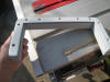
 |
I found the long bits at
McMaster Carr. |
 |
A
normal length tap would not work for such deep holes as the shank is
larger than the threads, which would damage the cut threads. What
you need is called a nut tap shown in the photo. The shank of the
nut tap is smaller diameter than the threads so the tap can cut as
deep into a hole as you need. Again, I found it at McMaster Carr. I
have used nut taps now for the hardware on the winch islands, the
stern chainplate, and most of the deck hardware--all areas that
exceed the depth of a standard tap. |
A tip
about the proper orientation for mounting a winch. If the winch uses a
pinion gear as mine do, the pinion should be in direct alignment with the
line coming to the winch, in this case the jib sheets. Aligning the pinion
this way minimizes the load on the gear housing, since the loads on the
pinion from the sheet are opposite to the load
 on
the pinion from driving the winch, like the photo on the right. If the winch
were aligned so the pinion was 180 degrees opposite, the loads would be
doubled on the gear housing, which could cause damage or even failure of the
winch. You can read more about winch alignment
here. on
the pinion from driving the winch, like the photo on the right. If the winch
were aligned so the pinion was 180 degrees opposite, the loads would be
doubled on the gear housing, which could cause damage or even failure of the
winch. You can read more about winch alignment
here.
 |
Here is starboard island drilled and tapped for the genoa winch. It
will take 3-1/2" machine screws to attach the winch. It helps when
positioning the winch, cleat or whatever over the potted holes to
draw a small cross hairs in the center of each hole--then you will
know when the object is centered correctly. |
 |
Here, the primary winch, a Barient 24 ST two speed, is mounted. |
 |
Here, the cleat has been mounted. |
 |
And the starboard secondary winch, a Lewmar 16 ST. |
 |
And the same for the port winch island. |
| |
|
Propane locker
I have
pondered the location of a propane locker for some time now: the lazarette
seems a logical place but building an air-tight locker inside the lazarette
seems awkward to use and that location would limit storage. I also
considered simply adding a tank onto the pushpit, but since I will be using
a propane stove and a propane fireplace, I will need more capacity than one
tank can provide, and having a tank on the stern deck is a little too trailerish for me. So I will build a locker under the aft area of the
starboard cockpit seat, aft of the bulkhead that encloses the quarter berth.
I'm not sure how big to build it, but these are the steps I will need to
complete:
-
Cut an
opening for an air-tight hatch in the cockpit seat
-
Install a hatch,
-
Clean
out the area under the hatch and define the sides of the locker,
-
Build
out the locker and define a hold-down method for the tanks
-
Install the tanks, regulator, solenoid and feed lines to the cabin.
I would
like to have the capacity for two 20# tanks, but their diameter is such that
I can't find an appropriate size hatch--so I settled on a Beckson 15" x 15"
hatch that gives an inside opening size of 11-1/2 inches--enough to fit 10#
or 11# tanks into. I will probably use three Trident steel 11# tanks which
will give me good capacity. I didn't have the height needed for the
11# vertical tanks, but I can nicely fit two 10# horizontal tanks in the
locker.
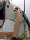
 First
I laid out the hole for the hatch in the cockpit seat. The hatch needs to be
inboard of the coaming enough to open at least 90 degrees and still fit the
seat. The Beckson First
I laid out the hole for the hatch in the cockpit seat. The hatch needs to be
inboard of the coaming enough to open at least 90 degrees and still fit the
seat. The Beckson
 hatch
just barely fits. A word about Beckson. I looked at a number of plastic
hatches and the Becksons were the only ones I found to be sturdy enough to
handle foot traffic and not flex. It is well hatch
just barely fits. A word about Beckson. I looked at a number of plastic
hatches and the Becksons were the only ones I found to be sturdy enough to
handle foot traffic and not flex. It is well
 made--in
Italy no less (a pleasure to find something not made in China!) and
reasonably priced. After drawing out the cut lines, I used a 2" hole saw to
cut the curved corners of the hole. The hole saw isn't mandatory but makes
nicer curves. made--in
Italy no less (a pleasure to find something not made in China!) and
reasonably priced. After drawing out the cut lines, I used a 2" hole saw to
cut the curved corners of the hole. The hole saw isn't mandatory but makes
nicer curves.
 I
discovered at this point that the cockpit seats are cored--very nice work on
Bristol's part! Then I cut two opposing sides with my jigsaw and temporarily
attached a support batten to keep hold up the area of the seat I was
removing. I
discovered at this point that the cockpit seats are cored--very nice work on
Bristol's part! Then I cut two opposing sides with my jigsaw and temporarily
attached a support batten to keep hold up the area of the seat I was
removing.
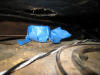
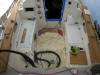
 The
finished hole was very close to fitting the hatch opening. Below the seat in
this area is where I had installed the compressor for the refrigerator. That
support structure--sturdy but not very attractive needed to be removed. You
can see the refrigerant lines as well as the seacock for one of the aft
cockpit drains. I will build the propane box around the seacock so I
can remove The
finished hole was very close to fitting the hatch opening. Below the seat in
this area is where I had installed the compressor for the refrigerator. That
support structure--sturdy but not very attractive needed to be removed. You
can see the refrigerant lines as well as the seacock for one of the aft
cockpit drains. I will build the propane box around the seacock so I
can remove
 it
if I ever need to. You can also see some spray insulation foam I applied
years ago. All that needs to be removed as well as a bit of the remains of
the ceiling liner. I used my Fein Multimaster to make very clean and
accurate cuts to get all that crap out of the area. Outboard of the
compressor support is the fuel water separator for the fuel tank vent line.
I will relocate this to somewhere else in the lazarette. I will need to
shift the exhaust hose and its outlet and the fuel vent from the starboard
side of the transom to the port side, since ABYC regs require at least 20
inches between the propane locker drain and any other opening to the boat's
interior. it
if I ever need to. You can also see some spray insulation foam I applied
years ago. All that needs to be removed as well as a bit of the remains of
the ceiling liner. I used my Fein Multimaster to make very clean and
accurate cuts to get all that crap out of the area. Outboard of the
compressor support is the fuel water separator for the fuel tank vent line.
I will relocate this to somewhere else in the lazarette. I will need to
shift the exhaust hose and its outlet and the fuel vent from the starboard
side of the transom to the port side, since ABYC regs require at least 20
inches between the propane locker drain and any other opening to the boat's
interior.
 After
cleaning up the interior area, I did the normal steps to prepare the hatch
opening: cleaning out the balsa core from the hole I cut, painting the balsa
with epoxy, and then filling the space with thickened epoxy. After
cleaning up the interior area, I did the normal steps to prepare the hatch
opening: cleaning out the balsa core from the hole I cut, painting the balsa
with epoxy, and then filling the space with thickened epoxy.
The next
step in the locker is to template the aft bulkhead to enclose the space.
Many thanks to
 my
brother John at this point for not letting me build the size that I wanted
but a more conservative space to hold to horizontal 10# bottles. I cut a
template out of cardboard and then cut the bulkhead out of some very my
brother John at this point for not letting me build the size that I wanted
but a more conservative space to hold to horizontal 10# bottles. I cut a
template out of cardboard and then cut the bulkhead out of some very
 nice
hardwood 1/2" plywood I found in the garage from a disassembled bunk bed I
made for the kids 20 years ago. The bulkhead fit flush to a 1/2" plywood
face I had glued to the lazarette side of the aft cockpit bulkhead years
ago, and enclosed the space. nice
hardwood 1/2" plywood I found in the garage from a disassembled bunk bed I
made for the kids 20 years ago. The bulkhead fit flush to a 1/2" plywood
face I had glued to the lazarette side of the aft cockpit bulkhead years
ago, and enclosed the space.
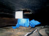
 In
order to get a close measurement of the floor of the locker, I used some
temporary battens as braces for the bulkhead which kept the bulkhead square
to the locker In
order to get a close measurement of the floor of the locker, I used some
temporary battens as braces for the bulkhead which kept the bulkhead square
to the locker
 space
(within a quarter of an inch) and allowed me to mount a small block with hot
glue as a more permanent brace. Once the space was defined and the bulkhead
screwed in place I had the final measurements for the bottom of the lock,
which I cut from the same 1/2" stock. space
(within a quarter of an inch) and allowed me to mount a small block with hot
glue as a more permanent brace. Once the space was defined and the bulkhead
screwed in place I had the final measurements for the bottom of the lock,
which I cut from the same 1/2" stock.
 With
the floor in place I could them accurately scribe a line under the edges of
the temporary braces to define the permanent cleat that would support the
floor on the bulkhead side. With
the floor in place I could them accurately scribe a line under the edges of
the temporary braces to define the permanent cleat that would support the
floor on the bulkhead side.
 I
painted both sides of the bulkhead and floor with unthickened epoxy to seal
the plywood from water, and while the epoxy was drying I painted out the
bottom area of the hull under the floor. By the way, I use modified epoxy
garage floor paint for as the general paint for the interior of the hull and
lockers. It hold tenaciously to otherwise grimy surfaces, and costs
considerably less than Bilgekote. I
painted both sides of the bulkhead and floor with unthickened epoxy to seal
the plywood from water, and while the epoxy was drying I painted out the
bottom area of the hull under the floor. By the way, I use modified epoxy
garage floor paint for as the general paint for the interior of the hull and
lockers. It hold tenaciously to otherwise grimy surfaces, and costs
considerably less than Bilgekote.
 Finally
I sealed the old remaining foam from the quarter berth bulkhead and any
openings I found with thickened epoxy, and glued and screwed the cleats in
place with Six10 epoxy. I will add fiberglass tape to all the corners and
joints of the locker and the fairing gives me a good surface to work from. Finally
I sealed the old remaining foam from the quarter berth bulkhead and any
openings I found with thickened epoxy, and glued and screwed the cleats in
place with Six10 epoxy. I will add fiberglass tape to all the corners and
joints of the locker and the fairing gives me a good surface to work from.
Before
final assembly and gluing I needed to determine the best location for the
drain and install the drain thru hull in the side of the locker. Using a
level I determined that the floor of the cockpit was upstream of where the
thru-hull will be in the transom, and locating the drain at
 the
outboard corner of the locker keeps the drain line against the hull/bottom
all the way back to the transom (and the most out of the way of damage by
gear in the lazarette). So I marked the bulkhead and drilled a 3/4" hole for
the 1/2" Marelon thru-hull. Then I cut off the flange of the thru hull on my
band saw and mounted it flush to the inside in epoxy thickened with 404 high
density adhesive filler. the
outboard corner of the locker keeps the drain line against the hull/bottom
all the way back to the transom (and the most out of the way of damage by
gear in the lazarette). So I marked the bulkhead and drilled a 3/4" hole for
the 1/2" Marelon thru-hull. Then I cut off the flange of the thru hull on my
band saw and mounted it flush to the inside in epoxy thickened with 404 high
density adhesive filler.
 Today
I finished up the propane locker. I tabbed all the interior seams and
tabbed the bulkhead Today
I finished up the propane locker. I tabbed all the interior seams and
tabbed the bulkhead
 to the hull, and cut the hole in the transom for the
drain thru hull. All
I have left to do is at some point paint it out inside and fill it with
water to test for leaks. Finally, I made a temporary top for the locker
until I paint the boat and install the Beckson hatch. to the hull, and cut the hole in the transom for the
drain thru hull. All
I have left to do is at some point paint it out inside and fill it with
water to test for leaks. Finally, I made a temporary top for the locker
until I paint the boat and install the Beckson hatch.
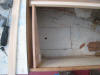
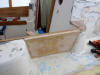
 |
Completed interior of
propane locker. All I have to do is mount the hatch on after the
decks are painted. |
 |
Completed locker bulkhead
in lazarette. |
Companionway Teak
 |
I
reattached the rails for the companionway drop boards. I made these
rails in 1990 and they have served me well. The rails are screwed
and glued in epoxy. I will bung the screw holes. |
 |
Here are the drop board rails with the bungs sanded smooth, waiting
for the first coat of epoxy. |
Anchor Chocks
While I
was busy working on the cockpit lockers I added chocks to hold two of my
primary bowers, a 22# Bruce in the starboard locker and a 25# Harborfast plow in the port
locker. The chocks for the two anchors will allow me to securely store them
when I am sailing on a passage or when the boat is in long term storage.
Once again, the chocks must meet my turn the boat upside down and shake
test; I certainly don't want either of these anchors breaking loose inside
the cockpit lockers.
|
TIP: How to Lube Marelon
Seacocks
Forespar, the maker and
distributor of Marelon seacocks is rather vague about the steps to lube
them. I have had these seacocks in my boat for the past 15 years and here
are the steps to correctly lube them.
Before I start, let me
state that Marelon seacocks are not plastic, nor are they delicate, nor do
they break, nor any of the other misinformed rumors that abound on sailing
forums. They are extremely tough as are all Marelon fittings but like any
seacock must be exercised and lubed occasionally.
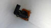
|
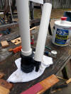 |
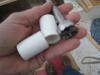
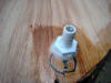
If you
have a Marelon seacock that seems frozen and will not actuate, here
is how to get it to work again. Use two sched 40 pvc pipes for some
leverage, remove the seacock and gradually work the lever open and
closed. |
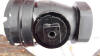
|
 |
Work some dabs
of
Lanocote around the edges of the ball valve. Lanocote is
recommended by Forespar and will last indefinitely. This photo shows
the bottom of the ball valve. |
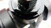
|
 |
Here is the top
of the ball valve as I work more Lanocote into it. |
|
 |
This is the one
area that is most often ignored and is the cause of the seacock
being very stiff to open or close: the actuating shaft that the ball
valve attaches to. Remove the handle and work a light machine oil
into the seal of the shaft. I use 3-in-1 oil. |
|
 |
Here you can
see where I am applying oil that gradually seeps down into the seal.
As you apply oil, continue to work the valve. The more you work it
the easier it will be to turn open and closed.
Lanocote and
3-in-1 oil work really well for the Marelon seacocks. Probably any
lube would, however, do not use any lube from an aerosol container,
as the propellant will damage the seacock.
Further reading:
What is Marelon? |
|