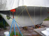
There is nothing particularly
interesting in the basic bottom job. To me it is the worst job in a
boatyard. In 1988 I sand blasted 20 years of bottom paint off the boat, and
applied an epoxy barrier coat. But not that much was known about barrier
coatings in 1988 and I didn't apply as many coats of epoxy as is recommended
by West Systems now. So I took these summer months when it is 120 degrees in
the cabin to rework the bottom the way it should be. The steps I followed
are shown on the right. I will show the details here of how to remove and
patch a thru-hull as I have removed and patched four of them and only added
one.
|
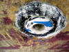 |
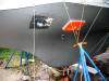
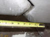
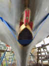
Here is the head discharge
thru-hull on the port side. It is a Forespar Marelon thru-hull, as
all the thru-hulls are. The trouble is it is located not in the head
area but under the port vee berth. So it needed to be moved.
|
|
 |
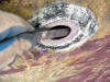
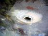
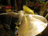
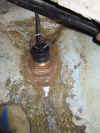
So, to remove, I took a
Japanese saw with zero kerf and sawed off the head of the thru-hull.
I assumed if would be a quick job, but the Marelon is really tough
stuff and took a long time even with a fresh saw. You can see the
tan colored 5200 under the head in this photo. Once the head is
removed it is not difficult to twist off the ball valve from inside
the hull and extract the remains of the thru-hull. |
|
 |
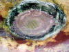
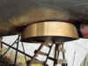
Once the 5200 is cleaned
off, take a rasp and bevel the outside edge all around to create a
bevel half the radius of the hole. |
|
 |
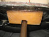
Now do the same bevel to
the inside of the opening. |
|
 |
I use three layers of 24 oz
biax mat and roving, each layer cut in a larger circle (the last
layers the diameter of the fully beveled edges to fill each side of
the opening. To help the layers stick, paint the edges with
unthickened epoxy first and wait until it just starts to kick.
|
|
 |
Before the biax dries hard,
add the first application of thickened epoxy and let it set for 48
hours before sanding. Use a high density filler. |
|
 |
Here is the first sanding.
|
|
 |
Fill again with low density
microballs to get the patch smooth as the surrounding hull. |
|
 |
Here are two thru-hulls on
the port bow patched, and one remaining thru-hull for a raw water
inlet faired. |
|
 |
One of the four cockpit
drain thru-hulls faired to the hull. |
|
 |
Here is the sink drain on
the starboard side patched and smooth, ready for barrier coating. |
This is a good venue to point out
some important elements of the rudder. After 20 or 30 years the rudder tends
to wear the pintel our of round, giving a vibration or shutter to the tiller
when the boat is sailing hard. It's nothing to worry about, and common with
keel hung rudders. If you wish to remove the rudder, follow this
write up.
You can get to the pintel by uncovering the mounting bolt (shown in the
photos below.
|
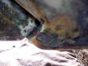 |
This is the starboard side
of the rudder and the rudder shoe. The red circle shows a hint of
the bolt that secures the rudder shoe pintel. The stainless bolt
mounts through the rudder shoe, and through a hole in the pintel,
locking it in place. The green line poorly represents the pintel's
position. |
|
 |
This shot shows the port
side location of the pintel mounting bolt. Both sides will be
covered (or should be) with polyester resin. Sand the area lightly
to reveal the bolt. Cover with epoxy when you are finished. |
One warning about the rudder and
rudder shoe;
When you are hauling your B29, be
careful not to allow the sling to be positioned under the rudder. If you
tell the yard that the rear edge of the sling should be a couple of inches
forward of the aft edge of the aft-most portlight, you will be safe. Just to
be sure as the travellift operator takes up slack in the slings, move the
tiller to be sure the sling isn't binding against the bottom edge of the
rudder. You will bend your rudder post if you let some idiot sling
under your rudder. By the same token, do not let your yard block your
B29 under the rudder shoe--it is strong, but not built for that sort of
stress. Be sure the rear edge of the block is a good 8 inches forward of the
shoe.
|
 |
Here is the starboard side
barrier coated with the West 422 stuff. The roll and tip dried very
smooth. |
|
 |
Looking forward.
|
|
 |
Here is the starboard side
with the first coat of Primocon. The primer went on very easily and
leveled nicely. I rolled and tipped it like I did with the epoxy.
The Primocon needs a lot of stirring as it looks like metallic paint
that needs constant mixing. It took almost a quart to do one side,
one coat. |
|
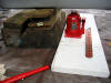 |
Once the bottom is
finished, I still need to move the blocks under the keel and the
jack stands. Here I am using a 20 ton low profile bottle jack to
lift the stern. |
|
 |
I used a piece of scrap
steel to spread the force evenly and a piece of cherry to protect
the keel. |
|
 |
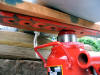
When I ordered my jack
stands from West Marine, I ordered 5 so I could do this: move any
stand and still have 2 supporting at all times on each side. |
|
 |
I used some 1-inch thick
Styrofoam under the jack stand bases to protect the finish. |
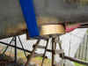
 Here
is my propeller. I just got it back from Hall's Propeller Shop in Christmas,
FL. They reduced the pitch by one inch, cleaned, balanced and polished it.
They have been caring for this propeller for the past 18 years and it is
still in very good shape. Here
is my propeller. I just got it back from Hall's Propeller Shop in Christmas,
FL. They reduced the pitch by one inch, cleaned, balanced and polished it.
They have been caring for this propeller for the past 18 years and it is
still in very good shape.
It is 12"
diameter by 15" pitch which with the Hurth 2.61 to 1 transmission on the
Yanmar 3GM30F, gives me hull speed at about 1800 rpm. It's a great little
prop. You can see that barnacles have taken a few bites in it. This refit I
am going to try a different procedure to keep anti-fouling paint on it. I am
using West Systems' method of epoxy bonding in which you first clean the
surface to be bonded with acetone, then immediately wet sand with epoxy to
work the epoxy into the metal. I have just finished that step in the
picture. Next I will paint on two coats of epoxy. Then add antifouling paint
when I am ready to launch. I'll let you know if it works.
More Rudder Details
At the
request of one Bristol 29 owner, currently in Guam, having destroyed the
bottom half of his rudder on a reef, I am including more detailed
information and dimensions for building a new rudder.
|
 |
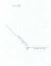
Overall photo of rudder. Rudder post is 1-1/4" solid bronze,
supported in three places: at the bottom where the rudderpost ends
in a hollowed out cup or gudgeon to receive the pintel. The pintel
is a 1/2" diameter pin rounded at the head to match with the gudgeon
that is let into the rudder shoe. It "floats" in this hole and is
secured with a 5/16" machine screw that passes thru a hole drilled
in the foot of the pintel. The length of the bolt is basically the
thickness of the rudder shoe. The second support is at the rudder
stuffing box at the top of the rudder post tube under the cockpit.
The third support is the cockpit sole rudderpost bearing. |
|
 |
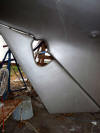
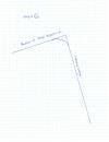
The height of the rudder shoe. |
|
 |
The length of the rudder shoe. |
|
 |
Detail of the top of the rudder. |
|
 |
Click these thumbnails to enlarge. Some detail as to the
rudder gudgeon and pintel. |
|
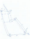 |
All the useful dimensions of the rudder including references to the
pertinent angles (circled letters). |
|
 |
Angle A is the angle at the aft bottom of the rudder. |
|
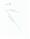 |
Angle B is the angle at the aft top of the rudder. |
|
 |
Angle C is the angle of the bottom of the prop aperture where it
joins the leading edge of the rudder. |
|
 |
Angle D is the angle of the rudder post with respect to the bottom
(horizontal) base of the keel. |
Installing
a New Depth Sounder Transducer
As part of this refit I decided to
remove the old depth sounder transducer and the speed log and replace them
with a combination Raymarine transducer. I cut a 2-inch hole straight thru
the keel in the bow cutaway, and shaped the area fair for mounting the
transducer.
 |
I built a small
fence in front of the transducer to prevent it from picking up any
weeds or line. |
 |
Another angle. |
 |
I used a nylon
collar to create a smooth, fair and square base. |
 |
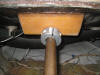
Here's the
transdsucer caulked and installed. |
|
-
Sand/scrape down to gelcoat.
-
Apply 3 coats of West
epoxy, roll and tipped, and sanded smooth.
-
Apply 3 coats of West mixed
with 422 Barrier Coat additive.
-
Apply 2 coats of
Interlux
Primocon primer.
-
Apply 3 coats of antifouling
paint.
How to Lube the Rudder
Pintel and Gudgeon
As I explain below, the pintel will
tend to wear in the gudgeon simply from hanging all these years. If you
don't tie off your rudder so it moves with the current, add a little sand or
mud from a close call grounding and the pintel can be ground away. The best
advice I have is to lube it. Here's how:
1. Buy a pinpoint grease injector
needle from McMaster Carr, like this one:

and attach it to your grease gun. If
you have an air powered gun, all the better.
2. Lift your rudder up to expose the
Pintel. Place some blocking under it so the rudder can't slip back down. You
should be able to expose almost all of the pintel.
3. Inspect the pintel for wear and
corrosion. Assuming it looks ok, insert the needle into the gudgeon cavity
and pump it full of grease.
4. Remove the blocking and ease the
rudder back down and rotate it from side to side to distribute the grease
evenly. Clean up the extra that squeezed out.
5. Do this at each haul-out when you
repaint your bottom.
How to Keep the Rudder from Rising and
Dislodging the Pintel
1. Build a collar base under the
cockpit sole at the rudder post top bearing that is a wedge the angle of the
rudderpost.
2. Mount it to
the underside of the sole around the rudderpost.
 |
The base is glued to the
underside of the cockpit sole in thickened epoxy. |
3. Attach a 1-1/4" collar zinc to the
rudderpost positioned 1/4" below the base. The zinc will prevent the rudder
from lifting.
 |
Here you can see the zinc
collar in place, about 1/4" down from the collar base. |
More info
about the cockpit, the rudder and the top rudder bearing is
here.
Info about the rudder stuffing box is
here. |