|
Building a Foredeck Dorade Box
I need a dorade box to vent the anchor
locker, so I built one today. I started by measuring how big I wanted it,
based on a dorade guard I purchased from marinershardware.com (now
bluewaterhardware.com) Then I rough
cut the sides, top, front and back panels. I decided I wanted to build this
dorade without screwing from the outside, necessitating wood bungs. I hate
using bungs if I don't have to on exterior wood. The box is glued together
and reinforced inside with 24 oz biax.
 I used 7/8"
teak so it very heavily constructed. The top, front, and back panels are
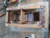
reinforced with scrap from the job. Here, the back is being glued in place
and you can see the reinforcing. The rule I use when gluing teak is to always
wipe the surfaces with acetone first; then paint each side with unthickened
epoxy; and then apply too much thickened epoxy with very slight clamping. I used 7/8"
teak so it very heavily constructed. The top, front, and back panels are
reinforced with scrap from the job. Here, the back is being glued in place
and you can see the reinforcing. The rule I use when gluing teak is to always
wipe the surfaces with acetone first; then paint each side with unthickened
epoxy; and then apply too much thickened epoxy with very slight clamping.
 You
can see the fillets of thickened epoxy here as well as the two drain holes I
bored. You
can see the fillets of thickened epoxy here as well as the two drain holes I
bored.
 Here
is the front panel clamped in glue. Here
is the front panel clamped in glue.
 Here
is the piece ready for the top. The top was about an 1/8" too short when I
cut the bevel for the front, but with sanding and shaping it came out fine. Here
is the piece ready for the top. The top was about an 1/8" too short when I
cut the bevel for the front, but with sanding and shaping it came out fine.
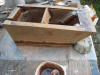
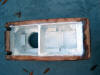
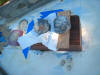
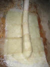
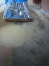
 Here
the top is set in glue. You can see how much splurges out, but the excess
epoxy makes a useful fillet. You can also see the fiberglass reinforcing,
and the baffle plate that keeps water out of the forward vent area. It all
looks pretty ugly now but will clean up very nicely. Here
the top is set in glue. You can see how much splurges out, but the excess
epoxy makes a useful fillet. You can also see the fiberglass reinforcing,
and the baffle plate that keeps water out of the forward vent area. It all
looks pretty ugly now but will clean up very nicely.
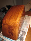
 Another
shot of the box. Another
shot of the box.
 I
finished rough sanding and shaping it here. I used a small belt sander
and a palm sander with 40 grit paper. I have just hosed off all the saw
dust. I
finished rough sanding and shaping it here. I used a small belt sander
and a palm sander with 40 grit paper. I have just hosed off all the saw
dust.
After the box dried, I sanded the
exterior progressively with 100, 180, 220 and 320 grit sandpaper. I wiped
off the surfaces carefully with acetone several times, and then painted on
two coats of epoxy to seal the teak.
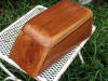
 Here
is the box after the second coat of epoxy. I will add one more coat and then
wet sand the surfaces smooth with 320 grit wet or dry. Here
is the box after the second coat of epoxy. I will add one more coat and then
wet sand the surfaces smooth with 320 grit wet or dry.
I wet sanded the box with 320 wet or
dry sandpaper, being careful not to break through the epoxy layer, just even
it out dead smooth. It is important to use a block to keep the cutting even.
If you use your fingers on the sandpaper you will eventually cut waves into
the surface. However, a trick I use is this: once the surface is cut down
smooth, if there are still some small depressions, I even then out using as
finger tip on the paper. The area is small enough that it doesn't show.
There are probably better ways used by professionals, but my way works, it's
faster and takes less coats of the finish to achieve a dead smooth surface.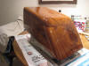
Here is the box with the third coat of
epoxy. I use a poly foam brush and it does a nice job. There are still
some very minor imperfections, but it's coming along.
 Here
you can get an idea of the the surface from the reflection. There are some
brush marks on the back that will have to be sanded out. Here
you can get an idea of the the surface from the reflection. There are some
brush marks on the back that will have to be sanded out.
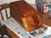
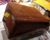
 Here
is another view. The reflection of the newspaper text is pretty clear. So
this is three full coats of epoxy. From now on I will add coats of System
Three water based LPU clear gloss. I will probably spray this dorade. Here
is another view. The reflection of the newspaper text is pretty clear. So
this is three full coats of epoxy. From now on I will add coats of System
Three water based LPU clear gloss. I will probably spray this dorade.
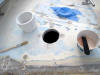
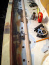
 Today
I laid out everything on the foredeck for the dorade, the dorade guard and
the mooring bit on the bow. I need to keep all of this gear as close to the
bowsprit as possible, to leave as much room as possible for deck storage of
a hard dingy. I am planning to build a dingy that is a bit over 7 feet long
which will mount between the dorade box forward and the mast aft. Today
I laid out everything on the foredeck for the dorade, the dorade guard and
the mooring bit on the bow. I need to keep all of this gear as close to the
bowsprit as possible, to leave as much room as possible for deck storage of
a hard dingy. I am planning to build a dingy that is a bit over 7 feet long
which will mount between the dorade box forward and the mast aft.
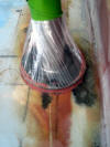
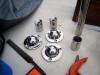 Here
you see the adjustable dorade guard bases I will use. The guard, cowl and
bases are from Mariners Hardware. They are all 316 stainless and beautifully
made and polished. Here
you see the adjustable dorade guard bases I will use. The guard, cowl and
bases are from Mariners Hardware. They are all 316 stainless and beautifully
made and polished.
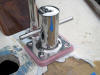 In
order to raise the mooring bit up more to the level of the bowsprit I
fashioned a base from fiberglass sheets from McMaster Carr. I will add
another 1/2' to the base, raising it to the level of the bowsprit. In
order to raise the mooring bit up more to the level of the bowsprit I
fashioned a base from fiberglass sheets from McMaster Carr. I will add
another 1/2' to the base, raising it to the level of the bowsprit.
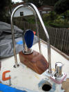
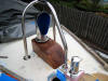
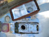
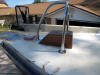
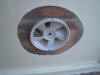
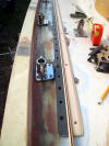
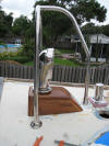 Here
is a side view of the box, cowl and guard. You can see how the adjust bases
mount as well. The guard needs to be cut down in height by about 5 inches. Here
is a side view of the box, cowl and guard. You can see how the adjust bases
mount as well. The guard needs to be cut down in height by about 5 inches.
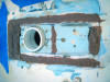
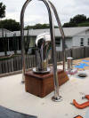 Another
angle of the assembly. You can see the drain holes in the back of the dorade
here. Another
angle of the assembly. You can see the drain holes in the back of the dorade
here.
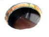
 Mariners
Hardware will paint the inside of the cowl with LPU to match your hull color
for only a few dollars. Very classy touch. Here, the guard has been trimmed.
It looks to make an excellent handhold as well, for working on deck. Mariners
Hardware will paint the inside of the cowl with LPU to match your hull color
for only a few dollars. Very classy touch. Here, the guard has been trimmed.
It looks to make an excellent handhold as well, for working on deck.
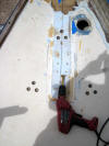 Now
that the positions are marked, I begin over boring all the mounting holes.
Here the holes are bored for the dorade guard bases. Now
that the positions are marked, I begin over boring all the mounting holes.
Here the holes are bored for the dorade guard bases.
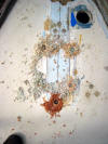 Here
the holes are bored to mount the dorade box from underneath. The darker
shavings from the bottom center hole are from the mahogany backing board
(instead of balsa) Bristol installed down the centerline of the deck. Here
the holes are bored to mount the dorade box from underneath. The darker
shavings from the bottom center hole are from the mahogany backing board
(instead of balsa) Bristol installed down the centerline of the deck.
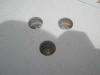 Beautiful,
bone dry, 40-year old balsa core. Very gratifying. Beautiful,
bone dry, 40-year old balsa core. Very gratifying.
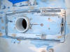
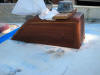
 This
is the underside of the finished dorade. eveything is painted out in two
coats of epoxy colored with white pigment. This
is the underside of the finished dorade. eveything is painted out in two
coats of epoxy colored with white pigment.
It seemed
a good weekend to attach the dorade to the foredeck. To
 begin,
I used the tip of my belt sander to cut begin,
I used the tip of my belt sander to cut
 thru
the gelcoat and get down to clean glass. I am going to glue the dorade
permanently to the foredeck; I have no reason to ever remove it and in its
vulnerable position I want it secured there as strongly as possible. thru
the gelcoat and get down to clean glass. I am going to glue the dorade
permanently to the foredeck; I have no reason to ever remove it and in its
vulnerable position I want it secured there as strongly as possible.
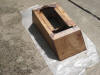
 Next
I cleaned the exposed glass and the adjoining edge of the teak with acetone
and let it dry. I painted both surfaces with unthickened epoxy and waited
about 15 minutes while I mixed up a very thick mixture of epoxy with 405
fillet adhesive. Next
I cleaned the exposed glass and the adjoining edge of the teak with acetone
and let it dry. I painted both surfaces with unthickened epoxy and waited
about 15 minutes while I mixed up a very thick mixture of epoxy with 405
fillet adhesive.
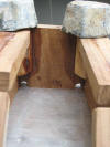
 I
ladled the mixture thickly along the marked surface of the deck and the
bottom edge of the dorade. Then I pressed the dorade down into the mix and
let it spluge out the sides all around (being careful to leave the drain
holes free at the back). I
ladled the mixture thickly along the marked surface of the deck and the
bottom edge of the dorade. Then I pressed the dorade down into the mix and
let it spluge out the sides all around (being careful to leave the drain
holes free at the back).
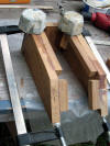
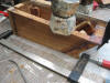
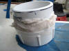
 I
cleaned up the excess epoxy with a mixing blade and put a couple of lead
pigs on top to hold it in I
cleaned up the excess epoxy with a mixing blade and put a couple of lead
pigs on top to hold it in
 position.
After a few days when the epoxy is fully cured I drill thru the pilot
holes from position.
After a few days when the epoxy is fully cured I drill thru the pilot
holes from
 underneath and screw in 4 1/4" self tapping machine screws just
for kicks. I don't think this dorade will be going anywhere. underneath and screw in 4 1/4" self tapping machine screws just
for kicks. I don't think this dorade will be going anywhere.
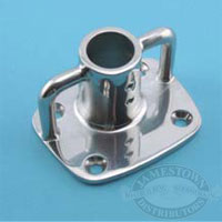
The final
step in securing the weatherdeck dorade is to assemble the
mounting sockets for the
dorade guard. The Mariners Hardware sockets articulate on a rounded top
so that it can assume any angle of the deck. You drill a hole thru the top
of the deck plate and bolt the plate to the socket.
 Here
I have mounted assembled the sockets, mounted them to the deck and epoxied
the guard tubes into the sockets. Here
I have mounted assembled the sockets, mounted them to the deck and epoxied
the guard tubes into the sockets.
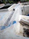
Building Deck Drains
B29s as
well as other older Bristols drain water off the decks thru inadequate
scuppers cut in the toerails. The areas of the scuppers weaken the toerails
which tend to split at those locations, the runoff from rain and pollution
streaks the topsides and there always seems to be a bit of standing water at
the aft most scupper (at least on my boat). So as a part of this refit I am
going to add proper deck drains. The drain will be flush with the deck
between the winch island and the bulwark, and drain down to a thruhull above
the waterline. I will use PVC piping for the majority of the drain hose,
permanently mounted to the inside of the hull and exiting thru a PVC elbow
epoxied in place. The PVC will be wrapped in fiberglass cloth, and the whole
thing will be tabbed heavily to the hull.
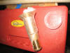
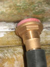
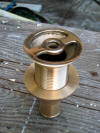 This
is one of two deck drain fittings I bought from Spartan Marine. It is cast,
polished bronze and costs around 70 dollars each. It takes a 1-inch drain
hose and the diameter of the flange is 2 inches. The flange, as you can sort
of see, is smooth and tapered. This
is one of two deck drain fittings I bought from Spartan Marine. It is cast,
polished bronze and costs around 70 dollars each. It takes a 1-inch drain
hose and the diameter of the flange is 2 inches. The flange, as you can sort
of see, is smooth and tapered.
 I'm
not sure how I would cut a bevel in the deck to match the tapered drain
flange, so the next best thing I can figure out is to use descending sizes
of forstner bits. Here you can see the steps of the descending sizes. Here,
I have wetted out the edge of the opening, preparing to make an epoxy mold
of the taper. I'm
not sure how I would cut a bevel in the deck to match the tapered drain
flange, so the next best thing I can figure out is to use descending sizes
of forstner bits. Here you can see the steps of the descending sizes. Here,
I have wetted out the edge of the opening, preparing to make an epoxy mold
of the taper.
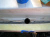 Here
you can see the hole in relation to the winch island and the bulwark. The
hole is positioned where the aft-most toerail scupper was. Here
you can see the hole in relation to the winch island and the bulwark. The
hole is positioned where the aft-most toerail scupper was.
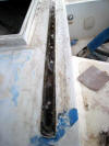
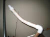 Here
is the assembled PVC drain pipe. PVC is easy to bend with some heat and I
bent the tube to the shape of the inside of the hull. After I glued the
fittings in place with thickened epoxy, I wrapped two layers of fiberglass
tape around it and left it to dry. Here
is the assembled PVC drain pipe. PVC is easy to bend with some heat and I
bent the tube to the shape of the inside of the hull. After I glued the
fittings in place with thickened epoxy, I wrapped two layers of fiberglass
tape around it and left it to dry.
 Here
is the hole (Gulp! I hate drilling holes like this!). The position of this
hole is about 3 inches up from the waterline and directly below the deck
drain. Here
is the hole (Gulp! I hate drilling holes like this!). The position of this
hole is about 3 inches up from the waterline and directly below the deck
drain.
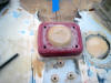
 To
make the epoxy mold of the taper I wrapped the drain fitting in kitchen
wrap. To
make the epoxy mold of the taper I wrapped the drain fitting in kitchen
wrap.
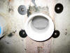
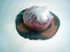
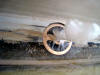 Here
you see the fitting in thickened epoxy. When it hardens I will tap the
fitting out with a hammer. Here
you see the fitting in thickened epoxy. When it hardens I will tap the
fitting out with a hammer.
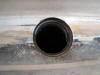
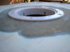
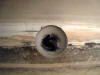 Here
is the tapered hole. Here
is the tapered hole.
 And,
here is the PVC elbow set in thickened epoxy from inside. I will sand the
fitting flush to the outside and fill the edges around it, And,
here is the PVC elbow set in thickened epoxy from inside. I will sand the
fitting flush to the outside and fill the edges around it,
 Here's
the elbow cut off flush, filled and sanded, ready for paint. Here's
the elbow cut off flush, filled and sanded, ready for paint.
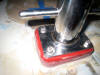
 You
can see the spacer I made from some sheets of fiberglass. It gives a smooth
bearing surface for the nut. You
can see the spacer I made from some sheets of fiberglass. It gives a smooth
bearing surface for the nut.
 I
sealed the drain flange with some of this stuff from Home Depot. It works
fine, is plenty cheap and allows removal of the fitting. I
sealed the drain flange with some of this stuff from Home Depot. It works
fine, is plenty cheap and allows removal of the fitting.
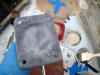
 This
shot shows the reinforcement inside the hull. It ain't pretty but with three
layers of 24 oz biax it's plenty strong. This
shot shows the reinforcement inside the hull. It ain't pretty but with three
layers of 24 oz biax it's plenty strong.
Installing a Weather Proof
Chainpipe
I followed this procedure for both the
chainpipe and for the foredeck dorade vent pipe. I want to be able to seal
the boat from extremes of water and seas and God forbid if I am capsized. So
I am using a standard schedule 40 PVC 4" pipe screw plug as a means of
sealing holes in the foredeck. The two dorades for the cabin top will be
sealed inside with brass 3" deckplates.
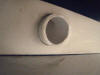
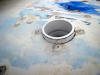
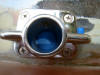
 I
cut the hole for the anchor deckpipe the size of the 4" PVC screw plug as
you can see in the photo. The inside diameter of the fitting is the same as
the ABI bronze anchor chain deck pipe. I
cut the hole for the anchor deckpipe the size of the 4" PVC screw plug as
you can see in the photo. The inside diameter of the fitting is the same as
the ABI bronze anchor chain deck pipe.
 I
wetted out the edge of the hole with unthickened epoxy. If you want you
could gouge out the balsa core and seal the edges with epoxy. I don't see
the need since I over bored where the holes will be and filled them solid,
and the PVC fitting inserted from below in thickened epoxy will nicely seal
the edges. I
wetted out the edge of the hole with unthickened epoxy. If you want you
could gouge out the balsa core and seal the edges with epoxy. I don't see
the need since I over bored where the holes will be and filled them solid,
and the PVC fitting inserted from below in thickened epoxy will nicely seal
the edges.
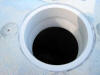
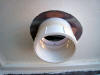
 Here,
I have buttered up the fitting with very thick epoxy. I will insert it in
this orientation from under the deck. The hole is just tight enough to hold
it in place until everything kicks. Here,
I have buttered up the fitting with very thick epoxy. I will insert it in
this orientation from under the deck. The hole is just tight enough to hold
it in place until everything kicks.
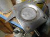
 It
is in place and nice fillet made on the underneath side. It
is in place and nice fillet made on the underneath side.
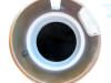
 And,
as you can see, I am filling from the top with a runny mix of epoxy. When it
all hardens, I will sand the top flush with the deck. To seal the hole, just
drop the chain to a hook I will install, and screw in a PVC cap from
underneath. And,
as you can see, I am filling from the top with a runny mix of epoxy. When it
all hardens, I will sand the top flush with the deck. To seal the hole, just
drop the chain to a hook I will install, and screw in a PVC cap from
underneath.
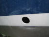
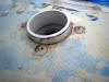
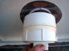
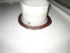
 Here
is the sanded flush version. Here
is the sanded flush version.
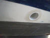
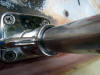
 And,
here is the bronze anchor chain hawse pipe in place. As you may notice, an
added benefit of using the PVC is it not only seals protects the vertical
edge of the deck, but prevents the chain from chafing the deck edge. And,
here is the bronze anchor chain hawse pipe in place. As you may notice, an
added benefit of using the PVC is it not only seals protects the vertical
edge of the deck, but prevents the chain from chafing the deck edge.
Installing a Nicro Solar Vent
I am installing two solar vents on the
Bristol, one in the lazarette hatch and one in the
head in front of the port
dorade box. The two solar vents are Nicro 2000 Day/Night vents. They each
move around 700 cubic feet of air each hour. Both vents will exhaust air
from the boat. The lazarette vent is vital to move air that has entered at
the anchor locker, and assisted by two additional fans, thru the boat under
the cabin sole, thru the engine compartment and out the lazarette, which
also houses the refrigerator compressor. Since I am planning some extended
offshore passages, I am building a system to seal both vents from
seawater--part of my policy during this refit that that
every opening in the boat needs to be completely sealable. Both Nicro vents
install thru a 4" deck plates. They snap in and look to be pretty stout once
they are mounted. The vents can be easily removed for bad weather by simply
snapping them out and sealing the deck plate with its snap-in cover. That is
fine for any sort of sailing I am planning around here--and will do fine
when preparing the boat for an approaching hurricane, but a plastic snap-in
covered deck plate is not stout enough for offshore, especially at the stern
of the boat. So, I am installing a 4" schedule 40
PVC screw plug, similarly to what I used to seal the foredeck dorade and the
foredeck chainpipe (explained above) on the underside of the lazarette
hatch.
First, i need to cut the hole in my lazarette
hatch. I built this hatch out of mahogany about 20 years ago, sealing it
inside and out with epoxy and covering the outside with several layers of fiberglass
cloth and epoxy.
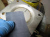
T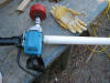 o
cut the hole for the Nicro deck plate, I am using a slightly modified drill.
The drill tends to buck and jamb when cutting with larger hole saws,
especially thru fiberglass, so for more control I added a longer arm to the
handgrip. o
cut the hole for the Nicro deck plate, I am using a slightly modified drill.
The drill tends to buck and jamb when cutting with larger hole saws,
especially thru fiberglass, so for more control I added a longer arm to the
handgrip.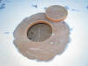 I cut the hole easily and cleanly by cutting thru both sides. The deck plate
has a slight bevel to the inside
I cut the hole easily and cleanly by cutting thru both sides. The deck plate
has a slight bevel to the inside
 top
flange, so I beveled the top edge of the hole slightly with a drum sander.
The deck plate fit nice top
flange, so I beveled the top edge of the hole slightly with a drum sander.
The deck plate fit nice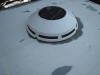 ly
with with no binding. Here is the vent test fitted. ly
with with no binding. Here is the vent test fitted.
 Here
is the inside of vent. Here
is the inside of vent.
 Then,
I began the procedure to mount the PVC cap to the inside of the hatch. The plug socket will be epoxied to the inside of the hatch. Then,
I began the procedure to mount the PVC cap to the inside of the hatch. The plug socket will be epoxied to the inside of the hatch.
 To
center the socket, I wrapped the hole saw I used in kitchen wrap. I painted
the adjoining surfaces with unthickened epoxy and let it sit a while. Then I
mixed a very stiff batch of epoxy thickened with 404 high density filler. I
set the socket down into a bead of the thick epoxy and To
center the socket, I wrapped the hole saw I used in kitchen wrap. I painted
the adjoining surfaces with unthickened epoxy and let it sit a while. Then I
mixed a very stiff batch of epoxy thickened with 404 high density filler. I
set the socket down into a bead of the thick epoxy and
 formed
a fillet around the perimeter. Then I gently removed the plastic wrapped
hole saw and let the thing harden. When the epoxy was at the soft set stage,
I laid around t formed
a fillet around the perimeter. Then I gently removed the plastic wrapped
hole saw and let the thing harden. When the epoxy was at the soft set stage,
I laid around t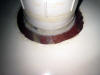 he
fillet two layers of 9oz tape. he
fillet two layers of 9oz tape.
Installing the Mooring Bit
Earlier I had built a 1-1/2" base for
the mooring bit, to bring it fair to the bowsprit. This I epoxied to the
deck. The mounting holes were over bored and filled with epoxy and threaded
for 5/16" hex head bolts. Now I want to mount the bit permanently to the
base. I will glue it to the fiberglass base with epoxy as well as attach it
mechanically with the bolts. The steps to bond steel to fiberglass is explained
in the West Systems bible. Here are the steps:
 First
clean the base you are bonding with acetone. Then apply First
clean the base you are bonding with acetone. Then apply
 unthickened
epoxy and sand it into the metal. Here I am using some emery cloth to work
the epoxy into the base. unthickened
epoxy and sand it into the metal. Here I am using some emery cloth to work
the epoxy into the base.
 Then
I sanded the fiberglass base which I h Then
I sanded the fiberglass base which I h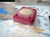 ad
previously molded the top to fit the underside of the bit. And, I applied
unthickened epoxy to it as well. ad
previously molded the top to fit the underside of the bit. And, I applied
unthickened epoxy to it as well.
 I
mixed up the rest of the epoxy with West 404 high density adhesive to a
slightly runny mix and applied I
mixed up the rest of the epoxy with West 404 high density adhesive to a
slightly runny mix and applied
 it
thoroughly to the base--I want it to squeeze out. Finally, I ran the bolts
in, tightened it down and carefully cleaned up the excess that squeezed out.
Once it is fully cured, I will add fender washers and nuts to the bolts
under the deck. it
thoroughly to the base--I want it to squeeze out. Finally, I ran the bolts
in, tightened it down and carefully cleaned up the excess that squeezed out.
Once it is fully cured, I will add fender washers and nuts to the bolts
under the deck.
Removing the Old Traveler Base
Since I have moved the traveler to the
cabin top, I decided to cut off
 flush
the base for the old traveler. It is just aft of the cockpit, forward of the
lazarette hatch. The base serves no purpose now and makes it apparent that
the traveler has been moved. So I will cut it off flush with the deck using
the Fein Multimaster. flush
the base for the old traveler. It is just aft of the cockpit, forward of the
lazarette hatch. The base serves no purpose now and makes it apparent that
the traveler has been moved. So I will cut it off flush with the deck using
the Fein Multimaster.
 Here
is the beginning of the cut. The Fein took about an hour to cut thru the
base. You can see what a clean thin kerf the saw makes. Here
is the beginning of the cut. The Fein took about an hour to cut thru the
base. You can see what a clean thin kerf the saw makes.
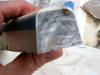 Here
is a cross section of the base. As you can see in the blurry photo (sorry)
the base is merely resin that was poured solid. Not very strong nor stable
which is why I would see hairline cracks radiating out from the bolt holes. Here
is a cross section of the base. As you can see in the blurry photo (sorry)
the base is merely resin that was poured solid. Not very strong nor stable
which is why I would see hairline cracks radiating out from the bolt holes.
 Finally,
after about an hour's work the base was cut away, leaving about a 1/8" lip
to sand flush. I over drilled the bolt holes, taped them from below and
filled the holes with epoxy slightly thickened with 404 high density filler.
Then I painted the cut area with the same mix. When it hardens I will sand
everything flush with my Festool rotary sander, lay on some fiberglass cloth and epoxy
that in place. Finally,
after about an hour's work the base was cut away, leaving about a 1/8" lip
to sand flush. I over drilled the bolt holes, taped them from below and
filled the holes with epoxy slightly thickened with 404 high density filler.
Then I painted the cut area with the same mix. When it hardens I will sand
everything flush with my Festool rotary sander, lay on some fiberglass cloth and epoxy
that in place.
Installing the Stanchions
I am installing 3 stanchions on each
side of the boat forward of the gates, instead of Bristol's usual two
stanchions. The locations are spread 4' between each, measured from the
forward gate. The stanchions are from Garhauer, welded with a similar
rectangular base to the original bases. For each base I locate the holes
with a centering bit, overbore the holes, fit 1/4" fiberglass backing
plates, fill the holes and drill and tap.
Today I sanded the filled holes down
level with the deck--about 10 minutes with the Festool--to discover that the
original stanchion bases on the gates were no longer flat. I guess 40 years
of pulling on the gates while boarding had misshapen the
 edges
and now they sort of wobble on the deck. So I ordered 4 of these Suncor
bases . They are cast 316 stainless and will work fine. About 30.00 from
Defender. My drilling and tapping will have to wait on receiving the new
bases since they are a slightly different size than the original Bristol
bases. edges
and now they sort of wobble on the deck. So I ordered 4 of these Suncor
bases . They are cast 316 stainless and will work fine. About 30.00 from
Defender. My drilling and tapping will have to wait on receiving the new
bases since they are a slightly different size than the original Bristol
bases.
Today I positioned the new stanchion
bases where I want the gate to be, and drilled potted and tapped the
mounting holes. To ensure a permanent and strong attachment, I potted the
gate stanchions into the bases in thickened epoxy.
 I
mounted the each base after taping over the bottom opening. I used one pump
epoxy thickened slightly with 404 high density adhesive I
mounted the each base after taping over the bottom opening. I used one pump
epoxy thickened slightly with 404 high density adhesive
 and
poured it into the base. Then I slipped he gate stanchion down all the way,
mounted the brace to the deck and horsed down on the two set screws in the
base. The amount of epoxy exactly filled the base to the top without running
over as you can see in the photo. and
poured it into the base. Then I slipped he gate stanchion down all the way,
mounted the brace to the deck and horsed down on the two set screws in the
base. The amount of epoxy exactly filled the base to the top without running
over as you can see in the photo.
 Once
the epoxy had thoroughly cured, Once
the epoxy had thoroughly cured,
 I
added a thickened epoxy base to the gate brace foot, which was slightly bent
from 40 years of wear. I wrapped the foot in Saran Wrap tightly to protect
it from the adhesive and remounted the gate. Then I simply cleaned up the
excess with my stirring stick. I
added a thickened epoxy base to the gate brace foot, which was slightly bent
from 40 years of wear. I wrapped the foot in Saran Wrap tightly to protect
it from the adhesive and remounted the gate. Then I simply cleaned up the
excess with my stirring stick.
 I
did the same to one of the uprights for the pushpit on the port side which
was a bit short. I am positive I will have to do some built up bases on the
starboard side of the pushpit as well. I
did the same to one of the uprights for the pushpit on the port side which
was a bit short. I am positive I will have to do some built up bases on the
starboard side of the pushpit as well.
Finally, I positioned and mounted the
three port-side Garhauer stanchions and then removed them for storage.
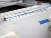
Installing the Genoa Track
 The
genoa track is a puzzlement: It needs to be longer than the original 4 ft.
stainless track, and since I am not mounting it on the caprail it will be
positioned inboard but as tight to the toerail as I can get it. I will also
build a stubbed toe preventer, a toe guard on the inside edge of the
track that will keep me from catching my toes and shoes on the track. The
track I am using is aluminum 1" T-track from Garhauer, 5 ft long. From
past experience I know that for the size genny I have, the genoa car is
normally positioned between the two sides of the lifeline gate so I kept the
track as tight to the gate bases as possible. The toe guard is just far
enough inboard of the track to allow free movement of the car without an
chafe. Finally, the only real tricky part in determining where to mount the
track is to ensure that the mounting holes are drilled on either side of the
aft port settee bulkhead. The
genoa track is a puzzlement: It needs to be longer than the original 4 ft.
stainless track, and since I am not mounting it on the caprail it will be
positioned inboard but as tight to the toerail as I can get it. I will also
build a stubbed toe preventer, a toe guard on the inside edge of the
track that will keep me from catching my toes and shoes on the track. The
track I am using is aluminum 1" T-track from Garhauer, 5 ft long. From
past experience I know that for the size genny I have, the genoa car is
normally positioned between the two sides of the lifeline gate so I kept the
track as tight to the gate bases as possible. The toe guard is just far
enough inboard of the track to allow free movement of the car without an
chafe. Finally, the only real tricky part in determining where to mount the
track is to ensure that the mounting holes are drilled on either side of the
aft port settee bulkhead.
 Once
I double-checked the final position, I drilled the potting holes for the
track and the mounting holes for the toe guard. The holes are all filled as
usual with epoxy mixed with 404 high density filler and once completely
cured re-drilled, and tapped. Finally I glued down the toe guard, which I
had cut from some clear poplar and shaped on the table saw. Later, I added
two coats of epoxy to the toe guard. Once
I double-checked the final position, I drilled the potting holes for the
track and the mounting holes for the toe guard. The holes are all filled as
usual with epoxy mixed with 404 high density filler and once completely
cured re-drilled, and tapped. Finally I glued down the toe guard, which I
had cut from some clear poplar and shaped on the table saw. Later, I added
two coats of epoxy to the toe guard.
After the potted holes fully cured, I
re-drilled them and tapped them for 1/4 x20 machine screws and mounted the
track. I then cut a backing plate from 3/8" fiberglass stock (from McMaster
Carr) and glued it to the underside of the deck using the track to locate
the holes for drilling. The backing plate was glued in place and the port
track complete. I repeated the process on the starboard side deck.. I am
using Lok-Tite exterior construction adhesive to attach the backing plates.
It grabs and holds instantly, it is tenacious stuff and significantly
cheaper than using 3M 5200. It cleans up with water. The holes in the
backing plate are drilled using a 5/16" bit so the hole size doesn't
interfere with the threaded track bolt.
|