|
This page encompasses all of the small projects I need to complete the
exterior of the cabin top, including, in no chronological or project based order:
Improving the Dorade
Boxes
The
Bristol dorade boxes are molded into the cabin top and are a distinctive and
identifying feature of Bristols. The trouble with the dorades is there is a
gap between the molded cabin top and the bottom layer of glass that
sandwiches the balsa core. That gap holds water, mold, mildew, dirt and God
knows what else. Additionally, the box itself is not as large as I would
like. SO as a part of this refit I will improve them by,
-
Filling in the "gap between the top layer of the cabin top and the bottom
layer so that no water can be trapped,
-
Covering with teak like a proper dorade should be, and
-
Strengthening the whole box so it can stand up to any seas.
I will
build a third dorade at the bow to ventilate the anchor locker.
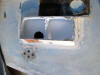
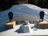
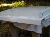
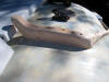
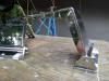
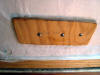
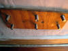
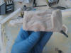
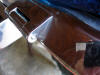
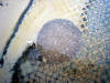
If you
ever wondered what the inside of your molded dorades looked like, take a
look at these shots:
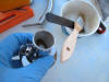
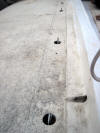
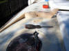
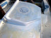
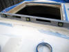
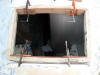
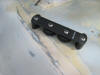
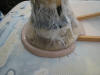
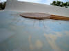
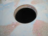
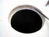
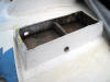  I
cut the top off the two dorades with a sawsall. The drains for the cowl side
of the dorade should be at the aft corners, not as they are. I
cut the top off the two dorades with a sawsall. The drains for the cowl side
of the dorade should be at the aft corners, not as they are.
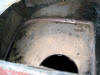
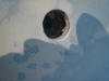
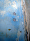
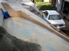
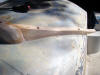
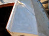
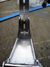
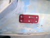
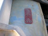
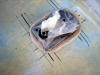
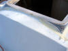
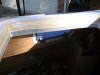
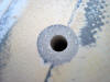
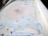
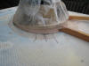
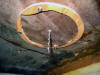
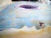
As I look at the dorades closer I
discover this:
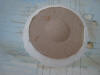
The dorade boxes
on the Bristol were made by molding the outer fiberglass skin in the shape
of the box, eliminating the core between the out and inner skins and
drilling a 3” hole in the inner skin into the cabin. The problem with this
design is that the base of the box is below the outer surface of the outer
skin, leaving a depression for water to collect and stand. To do it right, I
will need to cut off all of the structure of the box, fill the depression
with thickened epoxy and the build the box on top of the outer skin, like
a proper dorade box should be.
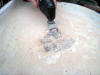
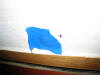
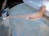
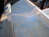
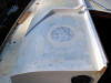
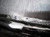
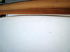
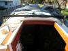
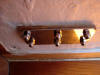
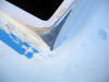
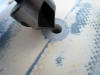
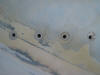
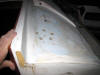
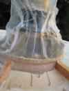
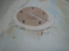
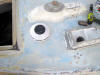
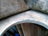 The
bigger problem with the dorades is the "gap" that you can see in this
picture. It goes about 3/4 of an inch up under the deck. The gap exists
around the entire box. The
bigger problem with the dorades is the "gap" that you can see in this
picture. It goes about 3/4 of an inch up under the deck. The gap exists
around the entire box.
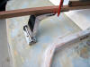
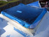
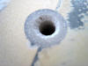
 I
filled it by first wetting it out with unthickened epoxy, I
filled it by first wetting it out with unthickened epoxy,
 then
packing some thickened epoxy into a caulking tube and running a bead all the
way around. then
packing some thickened epoxy into a caulking tube and running a bead all the
way around.
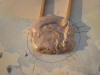
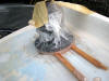
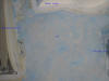
 When
the epoxy cures I will sand the insides smooth, paint them out and begin
covering the outside with teak. Stay tuned... When
the epoxy cures I will sand the insides smooth, paint them out and begin
covering the outside with teak. Stay tuned...
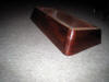
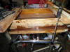
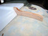
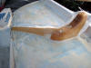
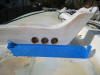
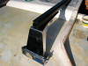
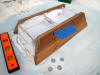 Here
I have started to cut and shape the teak to enclose the dorades. It is a
plethora of angles. Here
I have started to cut and shape the teak to enclose the dorades. It is a
plethora of angles.
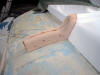
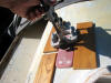
 After
the four sides are cut to all the After
the four sides are cut to all the
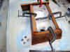 needed
angles I clamp them in place with some plastic kitchen wrap under the
corners. The plastic allows me to glue the sides clamped in place over the
fiberglass needed
angles I clamp them in place with some plastic kitchen wrap under the
corners. The plastic allows me to glue the sides clamped in place over the
fiberglass
 sides
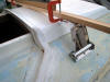
of the dorade, and remove it when the epoxy dries. Then, I trimmed the sides
with a Japanese saw, shaped it with my small belt sander and applied a first
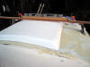
coat of epoxy thinned with acetone as a sealer. Before I can glue the dorade
in place and add the top I need to recut the 3" vent holes in the cabin top.
In preparation I glued in place two large pieces of 1/4" plywood. sides
of the dorade, and remove it when the epoxy dries. Then, I trimmed the sides
with a Japanese saw, shaped it with my small belt sander and applied a first
coat of epoxy thinned with acetone as a sealer. Before I can glue the dorade
in place and add the top I need to recut the 3" vent holes in the cabin top.
In preparation I glued in place two large pieces of 1/4" plywood.
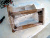
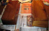
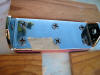
 Here
is the dorade frame with its first coat of sealer. Here
is the dorade frame with its first coat of sealer.
After building both dorade fames to fit
the existing fiberglass boxes, I finished a few small steps prior to fitting
the tops in place.
I glued 1/4 plywood in place under each
vent hole. The plywood will allow me to screw into place a 3" brass deck
plate so I can seal the vents from inside the boat.
I recut the 3" hole using a 3-3/8" hole
saw and sealed the edges of the fiberglass and plywood.
I glued a PVC stand pipe over the hole
in each dorade box.
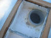 And
I glued nylon screening to the top of the stand pipe. When Olin Stephens
invented the dorade box he said firmly that screening was not necessary to
keep out mosquitoes because they prevented light from showing outside and so
the small bugs would not be attracted. I have glued screening to the three
dorades because I wish to keep out larger pests, especially roaches. And
I glued nylon screening to the top of the stand pipe. When Olin Stephens
invented the dorade box he said firmly that screening was not necessary to
keep out mosquitoes because they prevented light from showing outside and so
the small bugs would not be attracted. I have glued screening to the three
dorades because I wish to keep out larger pests, especially roaches.
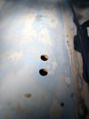
 Once
the glue for the screens dried, I bored new Once
the glue for the screens dried, I bored new
 drain
holes in each of the fiberglass boxes and in each teak box. Two holes, on
the aft face of each box, unlike what Bristol had built, allows the boxes to drain on either tack. drain
holes in each of the fiberglass boxes and in each teak box. Two holes, on
the aft face of each box, unlike what Bristol had built, allows the boxes to drain on either tack.
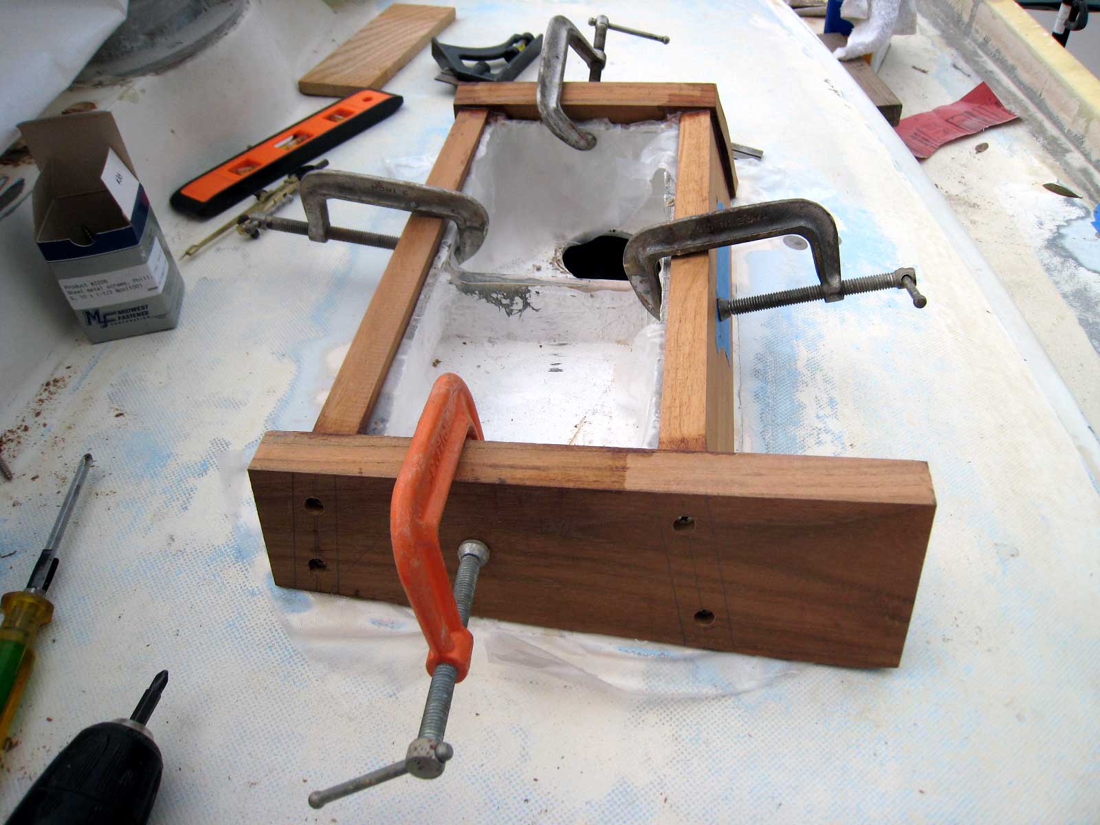
 I
prepared the top by first checking to see that each box was the same height
and level to the leveled hull. I
prepared the top by first checking to see that each box was the same height
and level to the leveled hull.
 They
are close enough for my tastes. Then I turned over the port box and set it
down into a They
are close enough for my tastes. Then I turned over the port box and set it
down into a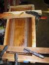 thick fillet of thickened epoxy. Once it was aligned and clamped, I added 9
oz fiberglass tape around all the seams.
thick fillet of thickened epoxy. Once it was aligned and clamped, I added 9
oz fiberglass tape around all the seams.
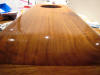
I spent a total of an hour sanding and
shaping the top to the already shaped box of the starboard dorade. I used my
Festool Rotex 150 which made amazing short and easy work of it. Some
pictures follow.
And here is the port dorade shaped and
ready to be mounted:
 Here
I have sanded them with 220 wet or dry and applied the first of three coats
of epoxy. I wet sanded the first coat with 320 grade abrasive and the
applied a second coat of epoxy. Here
I have sanded them with 220 wet or dry and applied the first of three coats
of epoxy. I wet sanded the first coat with 320 grade abrasive and the
applied a second coat of epoxy.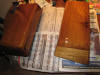
With two coats of epoxy on the two
dorade boxes I test positioned the dorades and the
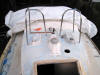 dorade
guards. The guards function as a brace for my butt when I am working at the
mast, as a means of keeping flogging lines from wrapping around the dorade
cowls, and as a guard to protect the cowls from the mainsheet, dorade
guards. The guards function as a brace for my butt when I am working at the
mast, as a means of keeping flogging lines from wrapping around the dorade
cowls, and as a guard to protect the cowls from the mainsheet,
 which
runs down from the boom to a turning block on the mast step. The photo on
the right shows the angle of the mainsheet with the boom extended. the sheet
will run free without chaffing the starboard guard. which
runs down from the boom to a turning block on the mast step. The photo on
the right shows the angle of the mainsheet with the boom extended. the sheet
will run free without chaffing the starboard guard.
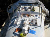
I installed temporarily the port dorade
box with the cowl just to get an idea of how everything will look. Here are
a few shots.
 Here
is one of the dorades after applying a second coat of System Three LPU clear
gloss. Here
is one of the dorades after applying a second coat of System Three LPU clear
gloss.
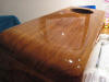 It
was applied over three coats of epoxy that I wet sanded to 320 grade. The S3
gloss is dry in this photo but hasn't yet been sanded. It
was applied over three coats of epoxy that I wet sanded to 320 grade. The S3
gloss is dry in this photo but hasn't yet been sanded.
The next step in improving the dorades
is to mount the dorade guards.
Previously
 I
overbored all the 18 mounting holes. Now I positioned each guard back in
place and carefully drilled the holes and taped each of them. I
overbored all the 18 mounting holes. Now I positioned each guard back in
place and carefully drilled the holes and taped each of them.
 I
used my portable drill press rig as I always do to ensure that I drilled
perpendicular to the surface of the cabin top. I
used my portable drill press rig as I always do to ensure that I drilled
perpendicular to the surface of the cabin top.
 I
used a 10-24 drill and tap set for them guard bases. Once all the mounting
holes were tapped and dry fitted the guards. Then, I removed the guards,
removed the bases and epoxied the bases to the guard tubes. I
used a 10-24 drill and tap set for them guard bases. Once all the mounting
holes were tapped and dry fitted the guards. Then, I removed the guards,
removed the bases and epoxied the bases to the guard tubes.
 These
guards are a life saving feature of the improvements to my boat I will be
trusting my life to them when I am offshore, so i will epoxy the tubes to
the bases and then drill the bases and thru-bolt them as well. These
guards are a life saving feature of the improvements to my boat I will be
trusting my life to them when I am offshore, so i will epoxy the tubes to
the bases and then drill the bases and thru-bolt them as well.
 Here
both guards are mounted and glued and I'm waiting for everything to dry.
Excuse all the clutter, After all the holes were drilled and tapped for the
guards, as well as for all the other holes in the deck and cabin top, Here
both guards are mounted and glued and I'm waiting for everything to dry.
Excuse all the clutter, After all the holes were drilled and tapped for the
guards, as well as for all the other holes in the deck and cabin top,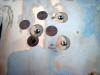 I bought some cheap screws at Home Depot and installed them to keep paint
from running down into the holes.
I bought some cheap screws at Home Depot and installed them to keep paint
from running down into the holes.
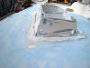
Remove the old
mainsheet winch base
Today, I began removing the mainsheet
winch base on the port
 side
of the cabin top. I will move the location of that winch aft and the winch
base only interferes. I began sanding it down with a very aggressive belt
sander, but my brother suggested using my Fein Multimaster with the flush
cutting blade. Wow, does that thing cut. We had the base removed in a matter
of minutes. I filled with thickened epoxy and will sand flush with the
surrounding cabin. side
of the cabin top. I will move the location of that winch aft and the winch
base only interferes. I began sanding it down with a very aggressive belt
sander, but my brother suggested using my Fein Multimaster with the flush
cutting blade. Wow, does that thing cut. We had the base removed in a matter
of minutes. I filled with thickened epoxy and will sand flush with the
surrounding cabin.
 Next
I over bored the screw holes when I will bolt the seahood to the cabin. The
screws set the proper angle for screwing up into the seahood, which has
already been overbored and filled with thickened epoxy, I poured thickened
epoxy around the screws and when the mix kicked I backed out the screws,
leaving the holes in the hardened glue. The holes will act as guides for my
tap later--I will tap and attach the seahood with 1/4"x2" machine screws
when everything is sanded and ready for paint. Next
I over bored the screw holes when I will bolt the seahood to the cabin. The
screws set the proper angle for screwing up into the seahood, which has
already been overbored and filled with thickened epoxy, I poured thickened
epoxy around the screws and when the mix kicked I backed out the screws,
leaving the holes in the hardened glue. The holes will act as guides for my
tap later--I will tap and attach the seahood with 1/4"x2" machine screws
when everything is sanded and ready for paint.
By the way, as a comparison to
the photo above showing the old dirty nonskid...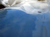 I
recently acquired a
Festool Rotex 150 orbital sander and used it for the first time
on the cabin I
recently acquired a
Festool Rotex 150 orbital sander and used it for the first time
on the cabin
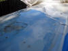 doghouse
nonskid. Even with the wrong abrasive paper for fiberglass, the tool
removed the nonskid and old Awlgrip paint in a matter of minutes
down to a finish the equivalent of 400 grit wet sanding. doghouse
nonskid. Even with the wrong abrasive paper for fiberglass, the tool
removed the nonskid and old Awlgrip paint in a matter of minutes
down to a finish the equivalent of 400 grit wet sanding.
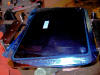
Painting the Companionway Hatch
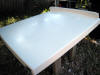 Today
I sprayed the companionway sliding hatch. The temperature was only in the
mid 60's, but System Three paint seems to thrive in cold weather: it flowed
very well. The base coats of Orcas White dried in about 20 minutes. It was
thinned 25 percent with water. Previously I had sprayed the hatch with
System Three WR-155 epoxy primer, and sanded lightly with 220 wet or dry. Today
I sprayed the companionway sliding hatch. The temperature was only in the
mid 60's, but System Three paint seems to thrive in cold weather: it flowed
very well. The base coats of Orcas White dried in about 20 minutes. It was
thinned 25 percent with water. Previously I had sprayed the hatch with
System Three WR-155 epoxy primer, and sanded lightly with 220 wet or dry.
 After
an hour of drying, I mixed 4 ounces of Gloss Clear crosslinked and sprayed
it over the base coat. Again, the clear flowed very well and dried to the
touch in an hour. Once the crosslinked coats have a week to dry and harden
completely I will mount the sliding hatch and the seahood over it and begin
building the dodger coaming down along each side of the doghouse. After
an hour of drying, I mixed 4 ounces of Gloss Clear crosslinked and sprayed
it over the base coat. Again, the clear flowed very well and dried to the
touch in an hour. Once the crosslinked coats have a week to dry and harden
completely I will mount the sliding hatch and the seahood over it and begin
building the dodger coaming down along each side of the doghouse.
Handrails
While waiting for the companionway
hatch to dry, I positioned
 and
drill holes in the dog house for the stainless handrails. I then over bored
each hole with a 3/4" spade bit thru the top layer of glass and the balsa
core, but not cutting thru the bottom layer of fiberglass. Then I used a
small screwdriver to dig balsa out wider than the bored hole. and
drill holes in the dog house for the stainless handrails. I then over bored
each hole with a 3/4" spade bit thru the top layer of glass and the balsa
core, but not cutting thru the bottom layer of fiberglass. Then I used a
small screwdriver to dig balsa out wider than the bored hole.
 Taping
over the inside of the hole prevents any drips. The adhesive on the tape
acts as a mold release and the glue will not stick to it. Taping
over the inside of the hole prevents any drips. The adhesive on the tape
acts as a mold release and the glue will not stick to it.
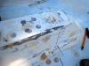
 Here
are some of the bored holes. Here
are some of the bored holes.
Here they are filled and ready for
first sanding.
 once
sanded completely smooth I will redrill the 1/4" holes to accept the
threaded studs of the handrails. once
sanded completely smooth I will redrill the 1/4" holes to accept the
threaded studs of the handrails.
Here a handrail is temporarily
mounted.
 The
forward handrail stud. The
forward handrail stud.
Building a Dodger Splash Coaming
The idea
of the coaming is to provide a lip to screw snaps into to attach the bottom
edge of a dodger and offer more protection from any spray or seas. The
coaming will extend the aft edge of the
seahood down each side of the cabin top to act as an attachment point for
the dodger. Now that I have the seahood finished and the companionway hatch
painted, they can be installed and accurate measurements taken for the
coaming.
I began by
marking the outline on the cabin: each side extends to port and starboard,
then takes an accurate angle aft to intersect with the cabinsides aft of the
rear portlight and in line with the forward cockpit coaming attachment.
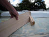
I used basswood and roughed out the shape on my trusty 12" band saw. It took
three attempts before I finally got what I wanted. The basswood will be
encapsulated in epoxy and i will add a layer or two of cloth to protect it.
 Here
you can see I have marked out on the cabin top the outline of the coaming. Here
you can see I have marked out on the cabin top the outline of the coaming.
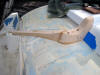
 The
port coaming roughed and positioned for fit. The
port coaming roughed and positioned for fit.
 The
starboard coaming. I've started to shape it with a rasp. The
starboard coaming. I've started to shape it with a rasp.
 Here
I am starting to shape the diagonal side rail. It has about as many angles
as you can imagine. I take off the curves with a compass and use my band saw
to do the cutting. Here
I am starting to shape the diagonal side rail. It has about as many angles
as you can imagine. I take off the curves with a compass and use my band saw
to do the cutting.
 Here
is the same diagonal, cut to fit, temporarily screwed down and set in
thickened epoxy. Here
is the same diagonal, cut to fit, temporarily screwed down and set in
thickened epoxy.
 Here's
the starboard side looking forward. When the epoxy is tack free, I'll add a
layer of epoxy in microballons to begin fairing it. Here's
the starboard side looking forward. When the epoxy is tack free, I'll add a
layer of epoxy in microballons to begin fairing it.
 Here
is the starboard coaming faired and ready for paint. Here
is the starboard coaming faired and ready for paint.
 Here
is the port dodger coaming roughly shaped and bedded in thickened epoxy. Here
is the port dodger coaming roughly shaped and bedded in thickened epoxy.
 Another
angle for the port coaming. Another
angle for the port coaming.
 Today
I added the first of two layers of 6oz fiberglass to the coamings. Today
I added the first of two layers of 6oz fiberglass to the coamings.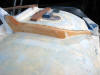 When
it hardened I trimmed off the scrap with a sharp knife, sanded the weave
down smooth and added a second layer of cloth. I will sand that smooth and
then paint the coamings with System Three epoxy primer. Then, all that is
left is to drill the holes for the lines that will feed the rope clutches
and the two winches. When
it hardened I trimmed off the scrap with a sharp knife, sanded the weave
down smooth and added a second layer of cloth. I will sand that smooth and
then paint the coamings with System Three epoxy primer. Then, all that is
left is to drill the holes for the lines that will feed the rope clutches
and the two winches.
Here are
the coamings primed with the first coat of System Three WR-155 water-based
epoxy primer.
 Here
I have bored the holes for the lines that run aft to sheet stoppers and the
port winch: the windward traveller car haul, the outhaul and the mainsheet.
I will add fairleads to the holes glued in thickened epoxy, then mount the
sheet stoppers and the winch, a Lewmar two-speed #16. Here
I have bored the holes for the lines that run aft to sheet stoppers and the
port winch: the windward traveller car haul, the outhaul and the mainsheet.
I will add fairleads to the holes glued in thickened epoxy, then mount the
sheet stoppers and the winch, a Lewmar two-speed #16.
Installing a Traveller Riser
Today I took off the measurements
needed to order and have built stainless steel risers to support the midboom
traveller. I am ordering these from
Garhauer
Marine. They build them to your custom specifications
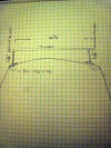 and
Garhauer does beautiful work at a very reasonable price. Here are the
measurements: and
Garhauer does beautiful work at a very reasonable price. Here are the
measurements:
This is
 what
the risers look like from the Garhauer catalog: what
the risers look like from the Garhauer catalog:
I ordered
the traveller risers from Garhauer at the Strictly Sail Miami boat show
yesterday. They should be here in a week.
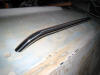
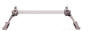
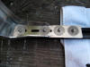
 The
risers arrived this afternoon and I thought I would share them with you.
These are the smaller of two models, designated UR1. They are
extremely beefy. They are custom made to my measurements, from a full 1/4"
stainless plate, with perfect welds and polished like chrome. They regularly
cost $170.00 for the pair in the Garhauer catalog. I got them for $150.00
including shipping at the Miami Strictly Sail boat show. It took a little
more than a month to get them. The
risers arrived this afternoon and I thought I would share them with you.
These are the smaller of two models, designated UR1. They are
extremely beefy. They are custom made to my measurements, from a full 1/4"
stainless plate, with perfect welds and polished like chrome. They regularly
cost $170.00 for the pair in the Garhauer catalog. I got them for $150.00
including shipping at the Miami Strictly Sail boat show. It took a little
more than a month to get them.
 Each
riser has a very classy Garhauer logo on it. You can judge the polished
stainless by the reflection here. Each
riser has a very classy Garhauer logo on it. You can judge the polished
stainless by the reflection here.
 Here
is the basic shape from the side view. The base pivots to account for the
curve of the cabin top. The horizontal plate is drilled for attaching the
traveller. You can use Garhauer's traveller if you want to buy their
traveller blocks. In my case, I already have a Harken Midrange traveller
system so I will attach it to these risers. Here
is the basic shape from the side view. The base pivots to account for the
curve of the cabin top. The horizontal plate is drilled for attaching the
traveller. You can use Garhauer's traveller if you want to buy their
traveller blocks. In my case, I already have a Harken Midrange traveller
system so I will attach it to these risers.
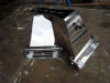
 Here's
the underside of the unit. As perfectly finished in brushed stainless as the
outside is polished. These are just gorgeous units. the workmanship in
Garhauer's products is first rate and their prices are really amazing. Here's
the underside of the unit. As perfectly finished in brushed stainless as the
outside is polished. These are just gorgeous units. the workmanship in
Garhauer's products is first rate and their prices are really amazing.
 Here
is a close up of on of the welds on the underside where they don't show. I
expected less than perfect welds here--it doesn't matter right? Wrong. The
welds are damn near perfect, as much as they are on the outside. Here
is a close up of on of the welds on the underside where they don't show. I
expected less than perfect welds here--it doesn't matter right? Wrong. The
welds are damn near perfect, as much as they are on the outside.
 Next,
I mocked up the traveller clamped to the risers to get an idea as to how
close my measurements were. I took a straight piece of trim and clamped it
to both risers. Then adjusted each riser so it was 7 inches in from the edge
of the cabinside. Next,
I mocked up the traveller clamped to the risers to get an idea as to how
close my measurements were. I took a straight piece of trim and clamped it
to both risers. Then adjusted each riser so it was 7 inches in from the edge
of the cabinside.
 The
results are exactly what I wanted. The bottom of the riser will be about
1/3" above the seahood. The
results are exactly what I wanted. The bottom of the riser will be about
1/3" above the seahood.
 Here
is the port side riser close to its final position. Here
is the port side riser close to its final position.
 Here
is the starboard side riser in position. Here
is the starboard side riser in position.
Since the cabin top is curved and the
attachment base of the risers is flat I felt I needed a flat bearing
surface. A midboom traveller must handle enormous forces: just think of a
jibe in heavy weather and you begin to understand the strains it must
absorb. I also believe midboom traveller risers are a common source of leaks
into the cored cabin top--they usually are not mounted correctly and become a
major source of leaks. So these risers will be mounted in a way that leaks
are impossible. The outer cabin surface and the inside cabin surface will be
flat so that the bearing surface of the mount and its associated backing
plate will have a full flat surface to bear against. Furthermore, the bolt
holes for the two riser brackets will be tapped to prevent any movement and
any egress of water.
The outside
riser base and the backing plate on the inside will be sandwiched between:
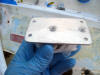
 For
the flat exterior pads, I cut some 1/4" fiberglass stock I have from McMaster Carr to
the shape of the backing plate, faired the edges, and mounted it to the
cabin top in thickened epoxy. For
the flat exterior pads, I cut some 1/4" fiberglass stock I have from McMaster Carr to
the shape of the backing plate, faired the edges, and mounted it to the
cabin top in thickened epoxy.
 On
the inside of the cabin I fashioned two 1/4" pieces of plywood and mounted
them in thickened epoxy. I did not tighten down the temporary attachment
screws so the pads would assume the curve of the cabin top; I purposely left
them flat. They will act as a spacer for the Formica overhead cabin panels to lie
against so that torque of the nuts on the backing plate do not stress or
crack the Formica. On
the inside of the cabin I fashioned two 1/4" pieces of plywood and mounted
them in thickened epoxy. I did not tighten down the temporary attachment
screws so the pads would assume the curve of the cabin top; I purposely left
them flat. They will act as a spacer for the Formica overhead cabin panels to lie
against so that torque of the nuts on the backing plate do not stress or
crack the Formica.
 Then
I overbored the mounting holes for the riser brackets and filled them with
thickened epoxy. The mounting brackets for the Garhauer risers are drilled
for 1/4" flathead bolts. Probably that is more than sufficient, but I
drilled out the holes to the next size, 5/16". The flatheads will stand a
little proud but I like the extra beef of the significantly larger bolts. Then
I overbored the mounting holes for the riser brackets and filled them with
thickened epoxy. The mounting brackets for the Garhauer risers are drilled
for 1/4" flathead bolts. Probably that is more than sufficient, but I
drilled out the holes to the next size, 5/16". The flatheads will stand a
little proud but I like the extra beef of the significantly larger bolts.
 I
ordered the new Harken traveller bar and received it today. It is very
stout, uses a continuous running bolt head slot on the underside and comes
with 8 I
ordered the new Harken traveller bar and received it today. It is very
stout, uses a continuous running bolt head slot on the underside and comes
with 8
 stainless
steel bolt head plates to fit into the slot. I ordered all stainless 316
hardware to attach the risers to the traveller. I used acorn nuts to create
a finished look to the underside and used blue Lok-Tite to keep everything
tight. In order to prevent any corrosion between the stainless risers
and stainless mounting bolts and the aluminum traveller, I coated the bolt
heads and the head plates that ride in the slot liberally with
LanoCote and also the underside of the traveller that touches the
risers. stainless
steel bolt head plates to fit into the slot. I ordered all stainless 316
hardware to attach the risers to the traveller. I used acorn nuts to create
a finished look to the underside and used blue Lok-Tite to keep everything
tight. In order to prevent any corrosion between the stainless risers
and stainless mounting bolts and the aluminum traveller, I coated the bolt
heads and the head plates that ride in the slot liberally with
LanoCote and also the underside of the traveller that touches the
risers.
 Here
is the port riser positioned on the mounting pad. Here
is the port riser positioned on the mounting pad.
 To
ensure I am drilling the mounting holes for the riser brackets square to the
mounting pads, I use a portable drill press jig I bought at Home Depot. I
mark the first hole, drill it, tap it, then mount the bracket and use it as
the template for the second hole. Remove the bracket, drill and tap the
second hole, remount the bracket for the third hole, etc. To
ensure I am drilling the mounting holes for the riser brackets square to the
mounting pads, I use a portable drill press jig I bought at Home Depot. I
mark the first hole, drill it, tap it, then mount the bracket and use it as
the template for the second hole. Remove the bracket, drill and tap the
second hole, remount the bracket for the third hole, etc.
 Here,
all the holes are taped and ready for the bracket. Here,
all the holes are taped and ready for the bracket.
 Here
is the bracket mounted in place with the 5/16 x 2-1/3 inch machine screws. Here
is the bracket mounted in place with the 5/16 x 2-1/3 inch machine screws.
 You
can see the screws protruding here. When the cabin is finished there will be
a sheet of Formica over the plywood base. You
can see the screws protruding here. When the cabin is finished there will be
a sheet of Formica over the plywood base.
 Everything
lined up very nicely. Here the backing plate from Garhauer is on just for
fit and the cap nuts are tightened down. Everything
lined up very nicely. Here the backing plate from Garhauer is on just for
fit and the cap nuts are tightened down.
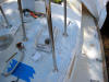
After positioning the traveller in
place, I used a 3/8" line to determine the exact positions for the
traveller car control line turning blocks. The line must exit to the
side of the traveller, down to a turning block to get the line parallel to
the cabin top, and then another turning block to turn the line 90 degrees to
lead thru the dodger coaming and eventually a winch. Here I have overboard
the holes for one of the four turning blocks--two per side. The Garhauer
turning blocks have the heads of rivets on the bottom so they do not sit
flush to the cabin, so I am going to build a base of epoxy for the to sit
on.
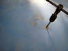
 Here
you can see the rivets (I have wrapped the turning Here
you can see the rivets (I have wrapped the turning
 block
in plastic wrap to keep it from sticking to the epoxy. Then I marked the
perimeter of the holes so I can find them after the epoxy base is finished.
Next, I mixed up a block
in plastic wrap to keep it from sticking to the epoxy. Then I marked the
perimeter of the holes so I can find them after the epoxy base is finished.
Next, I mixed up a
 very
thick batch of epoxy with 404 high density adhesive very
thick batch of epoxy with 404 high density adhesive
 filler
and buttered up the base of the turning block. I pressed the block down
exactly where I wanted it so the epoxy spluged out. I used the sharp edge of
the West stirring stick to clean up the excess epoxy and taped the turning
block in place. filler
and buttered up the base of the turning block. I pressed the block down
exactly where I wanted it so the epoxy spluged out. I used the sharp edge of
the West stirring stick to clean up the excess epoxy and taped the turning
block in place.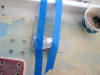 Tomorrow I will removed the blocks and drill and tap the holes for
fasteners.
Tomorrow I will removed the blocks and drill and tap the holes for
fasteners.
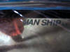
Installing the new Man Ship
Forward Hatch
My Hatch Arrives
Here are some pics of the custom-made
trapezoid
Bristol 29 hatch. If you are like me and dreamed of a weather proof,
sea-proof hatch, this is it folks. I can not begin to say enough good things
about Mariner's Hardware and Man Ship. take a look:
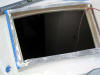
 It
is difficult to photograph, but this is the hatch right side up, still
wearing the UV protective film over the acrylic light. It
is difficult to photograph, but this is the hatch right side up, still
wearing the UV protective film over the acrylic light.
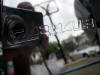
 You
can see the quality of the stainless (316), the welds and the polishing in
this shot. Here is one of the hinges with my Canon S-50 perfectly reflected.
The stainless looks like high quality chrome, only smoother and more
reflective. You
can see the quality of the stainless (316), the welds and the polishing in
this shot. Here is one of the hinges with my Canon S-50 perfectly reflected.
The stainless looks like high quality chrome, only smoother and more
reflective.
 Here
is the underside of the hatch. Notice the caulking detent built in to the
inner edge of the trim, the handles and the general high quality of the
workmanship. Here
is the underside of the hatch. Notice the caulking detent built in to the
inner edge of the trim, the handles and the general high quality of the
workmanship.
 The
Man Ship logo on the underside of the acrylic light. CE indicates a similar
European Union standard of quality to ISO9000. The
Man Ship logo on the underside of the acrylic light. CE indicates a similar
European Union standard of quality to ISO9000.
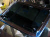
Installing the Forward Hatch
Today I prepared the raised forward
hatch combing to received the new hatch. The Bristol's combing is curved and
uses a curved fiberglass hatch that matches the crown of the cabin top.
 The
crown needed to be taken out of the combing in order to fit the new hatch. I
could have used a variety of tools--a The
crown needed to be taken out of the combing in order to fit the new hatch. I
could have used a variety of tools--a
 grinder
was suggested by my brother and a Sawsall comes readily to mind, but I wound
up using my trusty belt sander. It took about and hour and was very
controllable. I kept a level handy to act as a straight edge. I will have to
fill the weather stripping groove and bull nose the outboard edges of the
combing, but it will work just fine for the new hatch. Stay tuned for the
hatch installation next weekend. grinder
was suggested by my brother and a Sawsall comes readily to mind, but I wound
up using my trusty belt sander. It took about and hour and was very
controllable. I kept a level handy to act as a straight edge. I will have to
fill the weather stripping groove and bull nose the outboard edges of the
combing, but it will work just fine for the new hatch. Stay tuned for the
hatch installation next weekend.
Today I continued modifying the forward
hatch combing to receive the new hatch. After leveling it as best I could
with the belt sander, I dry fitted the hatch and marked low spots.
 I
puttied up the edges where I marked with thickened epoxy and sanded again.
Then I
puttied up the edges where I marked with thickened epoxy and sanded again.
Then
 I
took the belt sander to the sharp corners, rounding them and bullnosing the
exterior edge of the combing. The sander cut through into some voids in the
glass, which I later filled and faired with epoxy. Here is the hatch dry
fitted. I
took the belt sander to the sharp corners, rounding them and bullnosing the
exterior edge of the combing. The sander cut through into some voids in the
glass, which I later filled and faired with epoxy. Here is the hatch dry
fitted.
 The
combings are close to finished. They will received a coat of System Three
epoxy primer. Then I will screw down the hatch but not bed it yet, as I want
to remove it and the new ports when I paint the deck and cabin trunk. The
combings are close to finished. They will received a coat of System Three
epoxy primer. Then I will screw down the hatch but not bed it yet, as I want
to remove it and the new ports when I paint the deck and cabin trunk.
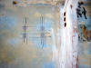
 I
also ground flat the famous Bristol hatch lips where the yard bonded the
cabin liner to the openings in the deck and cabin. It's always sort of an ugly,
rough way to finish the joints and is common to most Bristol's. Since I
am going to finish the inside of the hatch opening with cherry trim, it needs
to be flat (like it should have been 40 years ago). I
also ground flat the famous Bristol hatch lips where the yard bonded the
cabin liner to the openings in the deck and cabin. It's always sort of an ugly,
rough way to finish the joints and is common to most Bristol's. Since I
am going to finish the inside of the hatch opening with cherry trim, it needs
to be flat (like it should have been 40 years ago).
Today I did a number of small steps
toward getting the hatch installed.
Overbored all the mounting holes for
the hatch and filled with thickened epoxy.
Redrilled for the #12 x 1-1/2 in 316
stainless self tapping screws I ordered from McMaster.
Began dressing the inside vertical
sides of the hatch coaming with cherry.
Here are a couple of pics:
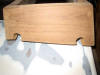
s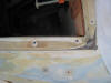 |
Here, the
mounting holes have been oveboard, filled and redrilled for the #12
screws. The holes have also been chamfered. |
 |
I painted the
backs of the cherry planks and the insides of the coamings with
unthickened epoxy, then added filler to make a peanut butter
consistency and buttered the backs of each board. |
Mounting Hardware on the
Cabin and Deck
this is the beginning of a description
of mounting hardware on the cabin and deck. The first being a
1. Spinlock turning block
 Here
you can see that I have overbored for a new Spinlock turning block that will
accept the mainsheet and the outhaul and route them back to the port side
cabin winch. I cannot stress the importance of overborning a cored cabin top
or deck. It is so easy there is no reason not to do it. The Spinlock
takes a 1/4" bolt, so I overbored with a 5/8" hole. I will redrill it
through now solid epoxy and it will never be stressed, or leak water into
the balsa core. It is 50 year solution and one that you should always do. Here
you can see that I have overbored for a new Spinlock turning block that will
accept the mainsheet and the outhaul and route them back to the port side
cabin winch. I cannot stress the importance of overborning a cored cabin top
or deck. It is so easy there is no reason not to do it. The Spinlock
takes a 1/4" bolt, so I overbored with a 5/8" hole. I will redrill it
through now solid epoxy and it will never be stressed, or leak water into
the balsa core. It is 50 year solution and one that you should always do.
Here's how
to keep water out of your coring:
 Fill
with thickened epoxy. Fill
with thickened epoxy.
 Drill
for the size fastener, in this case 1/4" holes. Drill
for the size fastener, in this case 1/4" holes.
 Use
a chamfered bore, like this to create a bevel edge to the hole. Use
a chamfered bore, like this to create a bevel edge to the hole.
 Like
this. The bevel will hold a nice bead of caulking that won't be squeezed out
when you tighten the fastener. Like
this. The bevel will hold a nice bead of caulking that won't be squeezed out
when you tighten the fastener.
 Holes
ready for the fasteners.. Holes
ready for the fasteners..
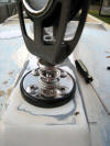
 Here's
the turning block mounted temporarily. Here's
the turning block mounted temporarily.
 The
bolts go through, washers and nuts with Lok-Tite added and the bolts cut off
flush with the bottom of the nut. The whole assembly is less than 1/4" thick
so it doesn't interfere with my overhead panels. Do this
with every fastener thru your cabin and deck and you will never never have a
problem with core saturation. The
bolts go through, washers and nuts with Lok-Tite added and the bolts cut off
flush with the bottom of the nut. The whole assembly is less than 1/4" thick
so it doesn't interfere with my overhead panels. Do this
with every fastener thru your cabin and deck and you will never never have a
problem with core saturation.
Cabintop Lewmar Winches
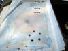 I
am mounting a Spinlock triple clutch and a Lewmar #16 two speed winch on the
port cabin top. The winch serves the mainsheet, the outhaul and the portside
traveller car haul. Here you can see I have overbored the mounting holes for
the rope clutches and the winch base. These will be filled and re-drilled
like the description above. The winch will be tilted aft 10 degrees and I
will make a tilted base out of thickened epoxy for it. I will install a
single clutch and a Lewmar #7 on the starboard to handle the starboard side
traveller car haul. I
am mounting a Spinlock triple clutch and a Lewmar #16 two speed winch on the
port cabin top. The winch serves the mainsheet, the outhaul and the portside
traveller car haul. Here you can see I have overbored the mounting holes for
the rope clutches and the winch base. These will be filled and re-drilled
like the description above. The winch will be tilted aft 10 degrees and I
will make a tilted base out of thickened epoxy for it. I will install a
single clutch and a Lewmar #7 on the starboard to handle the starboard side
traveller car haul.
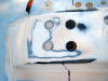
 Here
is the portside holes filled with the first filling and sanded smooth. Here
is the portside holes filled with the first filling and sanded smooth.
 Here
is the starboard side with the first filling. Here
is the starboard side with the first filling.
So I want to tilt the port winch ab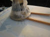 out
10 degrees to prevent overrides. If you read the West System manual, the
instructions are very detailed: it's easy and quick to do. The most
important step is to cover your winch base with some kind of release
agent--I use kitchen plastic wrap. The use a couple of scrapes of wood to
raise the forward edge, or the edge you wish to tilt. Mark everything with a
pencil so you can align it later--also an important step. out
10 degrees to prevent overrides. If you read the West System manual, the
instructions are very detailed: it's easy and quick to do. The most
important step is to cover your winch base with some kind of release
agent--I use kitchen plastic wrap. The use a couple of scrapes of wood to
raise the forward edge, or the edge you wish to tilt. Mark everything with a
pencil so you can align it later--also an important step.
 I
mixed up a 2 or 3 squirt mix of epoxy and 405 filleting adhesive filler to a
paste where the peaks would not fall off. Slop that into the middle of where
the base will be. I
mixed up a 2 or 3 squirt mix of epoxy and 405 filleting adhesive filler to a
paste where the peaks would not fall off. Slop that into the middle of where
the base will be.
 The
trick here is to position the winch correctly. The pencil marks are crucial.
make sure you put enough of a blob down that it fills under the winch base
entirely. Then when everything is positioned just so, take a stirring stick
or your finger and scrap up the excess that spluged out. The
trick here is to position the winch correctly. The pencil marks are crucial.
make sure you put enough of a blob down that it fills under the winch base
entirely. Then when everything is positioned just so, take a stirring stick
or your finger and scrap up the excess that spluged out.
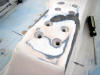
 Here
you see the edges filleted nicely, and the base ready to kickoff and harden.
I took a piece of tape from the companionway side to the top of the winch
just to secure it so it doesn't shift down the top of the cabin. Here
you see the edges filleted nicely, and the base ready to kickoff and harden.
I took a piece of tape from the companionway side to the top of the winch
just to secure it so it doesn't shift down the top of the cabin.
 Here
is a close up of the sticks and the epoxy fillet. I will clean everything up
and sand the excess epoxy smooth. I will fair out the fillet to blend it
more into the cabin top also. Here
is a close up of the sticks and the epoxy fillet. I will clean everything up
and sand the excess epoxy smooth. I will fair out the fillet to blend it
more into the cabin top also.
 .Here
I am building the epoxy base for the starboard winch that will control the
starboard traveller car haul. The winch is a Lewmar single speed #7. .Here
I am building the epoxy base for the starboard winch that will control the
starboard traveller car haul. The winch is a Lewmar single speed #7.
 You
can see the angle of the base here. I trimmed off the exposed sticks with a
chisel. You
can see the angle of the base here. I trimmed off the exposed sticks with a
chisel.
 I
have added the first application of epoxy thickened in microballs to build a
nice fillet around the base. I
have added the first application of epoxy thickened in microballs to build a
nice fillet around the base.
 And
here you can see I have drilled the mounting holes and cut a water drain
groove. The base is ready to paint. And
here you can see I have drilled the mounting holes and cut a water drain
groove. The base is ready to paint.
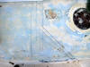
Installing a Solar Vent in the
Head
This is the second solar vent I am
installing; the other being in the
lazarette hatch. It is a Nicro 2000 Day/Night solar vent, requiring a
4-1/2" hole cut in the cabin top. I
 am
locating it forward of the dorade box and as close to the mast step as I can
get. Here is the mark on the cabin. I drilled a 1/4" hole at the mark to
confirm it was located ok inside the head. am
locating it forward of the dorade box and as close to the mast step as I can
get. Here is the mark on the cabin. I drilled a 1/4" hole at the mark to
confirm it was located ok inside the head.
 Then
I used the drill bit in the hole to locate the center of a plywood trim ring
I cut that will be used to mount a second deck plate inside the head. I
epoxied the trim ring in place. Then
I used the drill bit in the hole to locate the center of a plywood trim ring
I cut that will be used to mount a second deck plate inside the head. I
epoxied the trim ring in place.
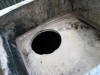
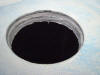
 The
I used my monster 1/2 drill and hole saw to cut the hole in the cabin top.
Once again it is The
I used my monster 1/2 drill and hole saw to cut the hole in the cabin top.
Once again it is
 very
reassuring to see bone dry balsa coring. I used a narrow chisel to dig out
the balsa from around the edge of the hole, back about 1/2". I thoroughly
wetted the balsa out with very
reassuring to see bone dry balsa coring. I used a narrow chisel to dig out
the balsa from around the edge of the hole, back about 1/2". I thoroughly
wetted the balsa out with
 unthickened
epoxy, and used a caulking tube to inject a very thick mixture of epoxy and
404 high density filler into the gap. unthickened
epoxy, and used a caulking tube to inject a very thick mixture of epoxy and
404 high density filler into the gap.
When the epoxy hardened I took a drum
sander on my drill and eased the top
 edge
for the deck plate and smoothed the vertical edge of the hole. Here you can
see that the deck plate fits flat against the cabin top in this area. edge
for the deck plate and smoothed the vertical edge of the hole. Here you can
see that the deck plate fits flat against the cabin top in this area.
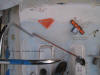
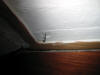
 Then
I test fit the solar vent. The location is ideal for me. I do very little
mast work on the port side of the mast and when I do I can comfortably
position the vent between my feet. Then
I test fit the solar vent. The location is ideal for me. I do very little
mast work on the port side of the mast and when I do I can comfortably
position the vent between my feet.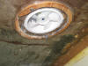 Here is a shot of the vent from inside the head. Still needs some work but I
am waiting on the interior deck plate first before I continue.
Here is a shot of the vent from inside the head. Still needs some work but I
am waiting on the interior deck plate first before I continue.
Mounting the Mainsheet Return
Block
The mainsheet comes off the boom at the
most forward block, and down to a standup block mounted on the mast step. I
call it the mainsheet return block since the sheet makes a turn around it
and leads back to the sheet stopper and winch at the aft end of the cabin.
Mounting the block is straight forward--it is the location where the
original block was, but I relocated it to the end of the mast step so it
makes a fair lead around the aft uprights of the dorade guards when the boom
is all the way eased.
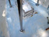
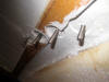
 First
I drilled oversized holes, in this case down about an inch to the steel
plate that is First
I drilled oversized holes, in this case down about an inch to the steel
plate that is
 part
of the mast step support system. I fill the holes with epoxy thickened with
West System 404 High density Adhesive. part
of the mast step support system. I fill the holes with epoxy thickened with
West System 404 High density Adhesive.
Then, I drilled a 7/32 tapping hole for
the tap thru the metal plate and down about 2 inches. The Garhauer block
accepted #10 screws for mounting,
 but
I drilled out the holes to accept 1/4 inch screws instead. I like the extra
beef here. but
I drilled out the holes to accept 1/4 inch screws instead. I like the extra
beef here.
 Then
I tapped the holes for 1/4 inch long 1-3/4 inch pan head machine screws. Then
I tapped the holes for 1/4 inch long 1-3/4 inch pan head machine screws.
|


